FREE 1 to 3-Day Delivery on Orders $149+ Details

How to Install Mammoth Adjustable Control Arms - Set of 8 on your Wrangler

Shop Parts in this Guide
Front Lower Control Arms:
Step 1:
Safely raise and support the vehicle on jack stands. Remove the wheels and tires. **Note: See the factory owner’s manual for recommended support locations.
Step 2:
Spray the upper and lower control arm nuts and bolts with penetrating oil to aid in the removal of factory hardware.
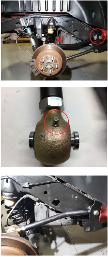
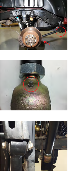
Step 3:
Using a 21mm socket and breaker bar, remove the axle side bolt on the front lower control arm. If equipped with cam washers, these will be reused. Save hardware as it will be used for reinstallation.
Step 4:
Using a 21mm socket and breaker bar, remove the frame side bolt, then remove the control arm.
Step 5:
Install the grease zerks ttings into the adjustable front lower control arms. Lengthen the new control arms to factory length. Then length or shorten the control to achieve the desired pinion angle for your application.
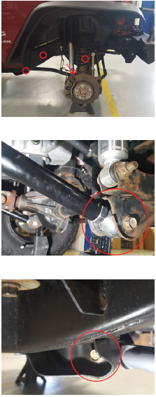
Step 6:
Using the factory hardware install the rubber bushing end of the control arm onto the frame bracket, ensure the bend of the control arm is to the inside for tire clearnace. Do not fully tighten the hardware until Step 8.
Step 7:
Using the factory hardware. Install the heim joint end of the control arm onto the axle side bracket. **Note: The heim ends are angled and will only t correctly on one side of the vehicle, pictured is the passenger side. Do not fully tighten the hardware until Step 8.
Step 8:
After the vehicle is on the ground at ride height, torque the axle side bolt to 117 ft-lbs, and the frame side bolt to 125 ft-lbs.
Front Upper Control Arms:
Step 1:
On the frame side, remove the 10mm bolt holding the heat shield to gain access to the upper mount bolt. Using a 18mm socket and breaker bar, remove the axle side and frame side upper control arm bolts. Remove the control arm from the vehicle. Factory hardware will be reused.
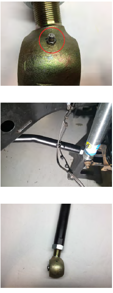
Step 2:
Install the grease zerks and plugs onto the adjustable front upper control arms. Lengthen the adjustable control arms to factory length. Then length or shorten the control to achieve the desired pinion angle for your application.
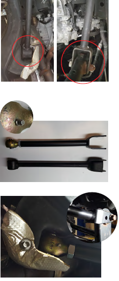
Step 3:
Using the factory hardware, install the heim joint side of the control arm into the frame bracket and the forked end, taper oriented as shown, onto the axle. Do not fully tighten the hardware until Step 4.
Step 4:
Once the vehicle is on the ground, torque all bolts to 75 ft-lbs.
Rear Lower Control Arms:
Step 1:
Using a 21mm socket and breaker bar, remove the axle size and frame side bolts of the rear lower control arm. Once the bolts are removed, remove the control arm.
Step 2:
Install the grease zerks and plugs onto the adjustable front upper control arms. Lengthen the adjustable control arms to factory length. Then length or shorten the control to achieve the desired pinion angle for your application.
Step 3:
Using the factory hardware, install the rubber bushing side of the control arm to the frame bracket. Install the heim joint side of the control arm to the axle mount. Do not fully tighten the hardware until Step 4.
Step 4:
Once the vehicle is on the ground, torque all bolts to 125 ft-lbs.
Rear Upper Control Arms:
Step 1:
Using a 18mm socket and breaker bar, remove the axle side and frame side bolts on the rear upper control arm. Then remove the control arm.
Step 2:
Install the grease zerks and plugs onto the adjustable front upper control arms. Lengthen the adjustable control arms to factory length. Then length or shorten the control to achieve the desired pinion angle for your application.
Step 3:
Using the factory hardware, install the rubber bushing side of the control arm to the frame bracket. Install the heim joint side of the control arm into the axle mount. Do not fully tighten the hardware until Step 4.
Step 4:
Once the vehicle is on the ground, torque all bolts to 125 ft-lbs.