 FREE 1 to 3-Day Delivery on Orders $149+ Details

How to Install KC HiLiTES 4 Cyclone LED Rock Light Kit - Amber on your 07-18 Jeep Wrangler JK; 2018 Jeep Wrangler JL
Thanks for choosing a KC HiLiTES product. We take pride in building the highest quality, best engineered systems possible. Your satisfaction with our product is important, so if you have any questions, please call our customer service line at 800-528-0950. For warranty information, visit our website at www.kchilites.com.
Busbar Installation
1. Find an appropriate location for the Busbar, within 12” of a common ground near the battery. Drill two 1/8”holes and using the supplied self-tapping screws, carefully secure the Busbar in place. (Note: on 2012 Jeeps, it is recommended that Busbar be secured to plastic partition separating the battery from engine.)
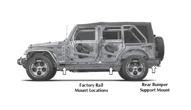
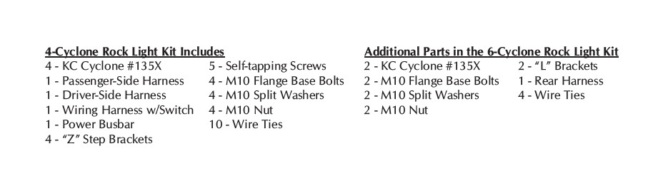
4-Cyclone Base Kit Installation
1. Locate the factory rock rail (or side-step) mounting locations closest to each tire, and one-by-one, using a 13mm socket, remove the factory rail mount bolts.
2. Re-install factory rail mount bolt with Z-Step Bracket, with the lower step (below the plane of the rail mount bolt) positioned towards the center of the vehicle, away from the chassis bolts.
3. Using the supplied M10 bolt and split washer, attach a KC Cyclone LED to the lower step of the bracket, securely fastening it with the M10 nut and Cyclone wire leads directed towards the sub-frame of the vehicle.
Driver-Side Harness Installation
1. Find the harness labeled DRIVER SIDE and position it so the Positive ( ) terminal can be attached to the Busbar and Negative (-) terminal can access a common ground.
2. Run the harness along the firewall of vehicle, following the factory wire-loom over the steering column and down to the sub-frame of vehicle, between factory heat-wrap and chassis.
3. Connect bullet terminals from first lead to Cyclone behind front driver-side wheel.
4. Continue to run the harness along the sub-frame & hydraulic lines and connect bullet terminals from second lead to Cyclone in front of rear driver-side wheel.
5. Using wire ties, secure the harness along hydraulic lines on the sub-frame, making sure the harness is neatly tucked away.
6. Connect Power ( ) terminal to Busbar and Negative (-) terminal to common ground.
Passenger Side Harness Installation
1. Find the harness labeled PASSENGER SIDE and position it so the Positive ( ) terminal can be attached to the Busbar and Negative (-) terminal can access a common ground.
2. Following the factory wire-loom, run the harness down to the passenger-side of the vehicle along sub-frame.
3. Connect bullet terminals from first lead to Cyclone behind front passenger-side wheel.
4. Continue to run the harness along the factory wire-loom on the sub-frame.
5. Connect bullet terminals from second lead to Cyclone in front of rear passenger side wheel.
6. Using wire ties, secure the harness to the factory wire loom, making sure the harness is neatly tucked away.
7. Connect Power ( ) terminal to Busbar and Negative (-) to common ground.
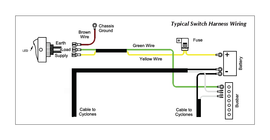
Switch Harness Installation
1. REMOVE THE FUSE FROM THE YELLOW WIRE . . . Find a suitable location inside the passenger compartment for your switch. To use optional KC panel, mark and drill two 1/8” holes, insert screws and loosely install the panel to ensure fit. Remove panel, install switch, and slide panel with switch back in place. (Do not tighten. The panel and switch will be removed when attaching wires.)
2. Attach the ring terminal of the YELLOW wire to the positive side of the battery or 12V power source. Attach the ring terminal of the GREEN wire to one of the end terminals on the Busbar.
3. Route the other end of the YELLOW and GREEN wires of the harness along the factory wire loom, through the firewall and into the vehicle toward the switch. Once the wires are inside the vehicle near the switch, remove the panel with switch and attach the GREEN wire to the switch terminal marked LOAD. Attach the YELLOW wire to the switch terminal marked SUPPLY. Attach one end of the BROWN wire to the switch terminal marked EARTH and the other end to a good grounded metal surface under the dash. (use supplied screw if needed) Re-attach the panel with switch and tighten the screws.
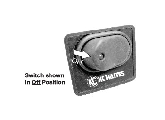
4. Before replacing the fuse, ensure the switch is in the off position (see below). Replace the fuse and turn on your lights. (If adding the 2 rear rock lights, continue below before replacing the fuse.)
2-Cyclone Rear Rock Kit Installation (5th/6th Cyclone if purchased)
1. Locate the 2-bumper shroud mounting brackets on inside of bumper support subframe:
2. Using a 13mm Socket, remove the factory bumper support bolts.
3. Re-install factory rail mount bolt with the supplied L-Brackets, with the lower step
(below the plane of the sub-frame) positioned towards the center of the
vehicle.
4. Using the supplied M10 bolt, attach a KC Cyclone LED to the lower step of
the bracket, securely fastening it with the M10 lock washer and nut. Ensure the
Cyclone wire leads are directed towards the sub-frame of the vehicle.
5. Find the harness labeled REAR and connect the harness to the pre-installed passenger side harness via the
DT-connector.
6. Run the harness along the sub-frame to the back of the vehicle.
7. Connect bullet terminals from first lead to the rear passenger side Cyclone.
8. Continue to run the harness along the sub-frame to the 2nd Cyclone and connect bullet terminals
9. Using wire ties, secure the harness along the sub-frame, making sure the harness is neatly tucked away.
YOUR DONE. Replace the fuse and light ‘em up.
