FREE 1 to 3-Day Delivery on Orders $149+ Details

How to Install MCE Gen-II Flexible Flat Fenders - OE-Style Finish on your Wrangler
Installation Time
2 hours
Tools Required
- 10 MM socket with at least 3” extension for OE fender bolts
- Long nose pliers or channel locks for OE fender clips
- Cutting tool (reciprocating saw, cut off wheel, ect.) for inner splash guard modification
- Drill
- 1/4” drill bit
- 5/32” allen wrench
- 1/8” allen wrench
- 7/16” end wrench
- 3/8” end wrench or socket
- Phillips # 2 screw driver or driver socket and socket wrench
- 9/64 inch drill bit
- Plastic clip pry tool
- Clamps (minimum of 2)
- Silicone RTV
1. Unplug OE corner marker light
Reach up into the fender and grab the back of the OE light socket. Twist ½ turn and pull out. Remove the plastic clips holding the wiring loom to the OE fender.
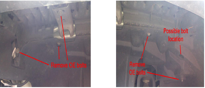
2. Unbolt OE fender
Depending on model year, there are varying amounts of bolts. Some have 5 bolts, other have a 6th bolt hidden up in a hole in the inner splash guard.
3. Remove OE fender from vehicle
Grab the fender at the bottom where it meets the rocker panel. Using a quick motion, pull up and outward at the same time. The fender will pop off it’s OE plastic clips.
4. Remove OE fender clips from vehicle
Using the pair of long nose pliers or channel locks, reach behind the clip and squeeze the two flared flanges together. Simultaneously, pull the clip out from the body by twisting and pulling.
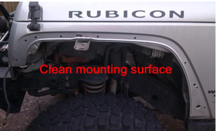
5. Clean vehicle mounting surface
Clean the accumulated dirt from the fender mounting flange.
6. Install MCE Generation II Fender
Taping the nuts to the back side of the holes on the vehicle will aid installation. Hold the fender up to the body in position. Except for the front two fasteners, install the button head fasteners through the holes and attach the nuts. Do not tighten fully until all of the bolts are installed. With the nuts not fully tightened, the fender placement can be adjusted on the vehicle for best fitment. A 1” long fastener can be used on the lower most bolt to aid in getting the nut started. Do not fully tighten yet.
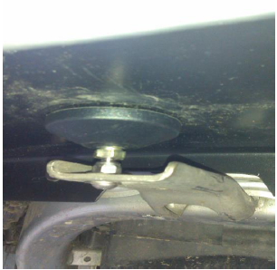
7. Install 1” button head bolt onto OE fender brace
Insert the bolt with washer upside down through the bottom of the brace. Tighten the nut and washer. This will become a stud to mount the fender pad.
8. Install fender mounting pad
Lift up on the MCE fender enough so that the pad can be threaded onto the bolt. Thread the pad all the way until it bottoms out. Then, back the pad up so there is slight preload on the MCE fender. (Only a few turns, if any, will be required, depending on vehicle manufacturing tolerances) This is engineered to be one of the two items which, due to true flat fender style design, prevent the fender from any possible fluttering at high speeds. Make certain that the pad has adjusted itself on it’s ball and socket joint so that it is sitting flat on the fender surface. Wait until the other side is installed, then make sure both fenders are preloaded the same amount when viewed from the front of the vehicle. If there is enough thread showing, install the ¼ - 20 nut to lock the pad in place.
9. Install front support bracket
This bracket is the second of two engineered items which prevent any movement at high speed. Install the bracket onto the front two fastener holes on the fender, using 1” long fasteners and fender washers. The bracket will have slop in the fastener holes so that the bracket can be adjusted so the front flange is mounted perfectly flat against the fender surface. If it is not mounted properly, it can preload the front surface of the fender slightly and not look right. Do not tighten nuts fully yet. Wait until the other side is installed, and both are adjusted/preloaded the same amount when viewed from the front of the vehicle.
10. Move to other side, remove OE fender and install MCE Generation II Fender
In the same manner as above, remove the other OE front fender, and install MCE fender, mounting pad, and front bracket.
11. Make sure both fenders are preloaded the same amount
Standing in front of the vehicle, make sure both fenders look symmetrical. If need be, adjust the pad preload slightly so that they are symmetrical. Preload should not exceed a slight upward pressure.
12. Tighten the front support brackets, all nuts, and drill fastener hole in MCE fender
Do this only after ensuring the front flange is touching flat against the front surface of the fender. From inside the wheel well underneath the fender, drill a ¼” hole through the hole in the bracket and into the fender surface. Install the 10-24 size button head bolt. Wing nuts are provided for quick removal of these bolts, allowing full elasticity of the fender for off-road. Or, the Nylock nuts can be used and easily removed with a wrench for less frequent trips.
The next steps are for modifying and installing the OE inner splash guards (strongly recommended in front applications)
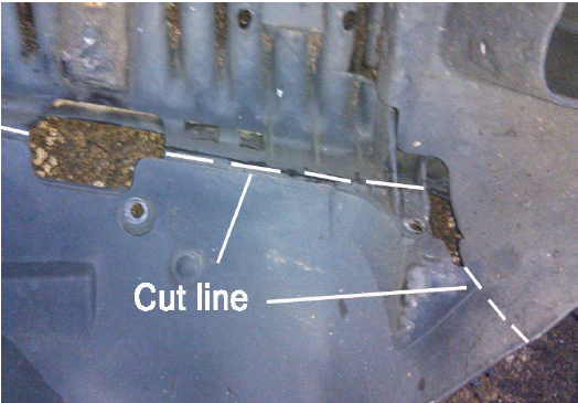
13. Scribe a cut line
*We are essentially trimming away the portion of the splash guard that is directly below the OE plastic fender. Or in other words, retaining only the amount which is housed within the vehicle sheet metal body.
Starting from the lower edge of the OE fender/splash guard combo, scribe a line from the inner edge of the OE fender. Make this line go from the bottom of the splash guard, all the way to the top corner where it meets the solid plastic OE fender brace. Continue scribing the line onto the OE fender brace. (It will be at the point of the 90 degree bend). Then, mark the front line as shown in the below figure. Also note to from the below figure that the rear portion of the solid plastic brace gets completely trimmed away.
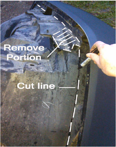
14. Cut along the lines
Using the cutting tool of your choice, trim the splash guard.
15. Install splash guard
Install the trimmed splash guard by pushing it into place. The MCE fender has a lip which will retain the splash guard, so the splash guard must be pushed far enough inward that it will go behind the lip on the MCE fender. Next, install the OE 10 MM bolts into the remaining holes in the splash guard.
16. Modify and install splash guard on other side of vehicle
Modify and install the splash guard in the same fashion as above.

1. Remove OE Flare
There are 5 round plastic clips in the inside of the wheel well. Pry these out. Next, grab one end of the OE flare at the bottom, and using a quick motion, pull upward and outward. Multiple pulls may be needed to remove the entire flare. This pulls the OE flare out of it’s plastic clips.
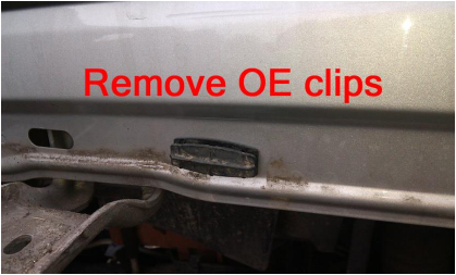
2. Remove OE Flare Clips
Using a plastic clip pry tool, or another prying device such as a large flat head screw driver, pry out the OE flare clips.
3. Clean vehicle mounting surface
Clean the accumulated dirt from the fender mounting flange.
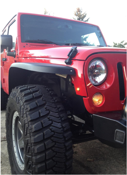
4. Install MCE Generation II Flare
***It is important to note that due to OE tolerances, as well as any possible prolonged pressure on the MCE flare during packaging/shipping, etc., there may be a small amount of pressure needed to get the MCE flare properly even with the vehicle’s sheet metal. Do this the following way:
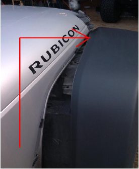
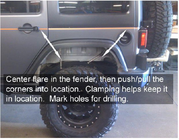
(Refer to FIG 1)
Center the MCE flare in the vehicle’s recessed flare mounting area. Then, starting with the front most or rearmost corner, either push or pull (whichever is necessary) the top corners of the flare to line up with the corner of the recess of the vehicle’s sheet metal. Ensure that the top surface and corner of the flare lines up with the edge of the vehicle’s sheet metal recess, then clamp the flare in place and mark the top holes.
Position the downward portions of the MCE flare (portions in front and behind the tire) so they are also tight and in line with the edge of the vehicle’s sheet metal recess edge, and mark the holes.
Remove the flare and pilot drill all marked holes to 9/64.
Place the flare back in place and drive in all self tapping fasteners with washers, but do not tighten yet. Once all fasteners have been started, then it is ok to tighten them.
NOTE: Placing a dab of silicone RTV on the tip of the fastener before installing will seal and ensure the vehicle’s sheet metal will remain rust free.
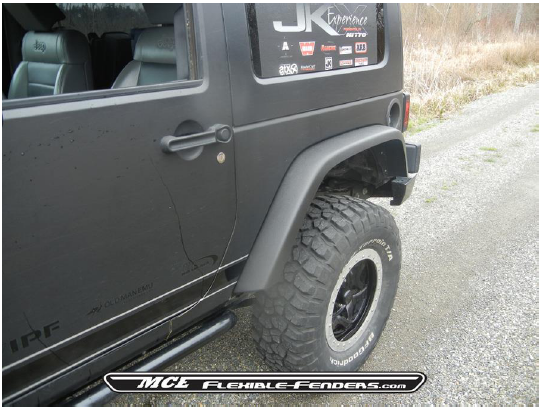
5. Install Flare on Other Side
In the same manner as above, remove the other OE flare, and install MCE flare in the same fashion.
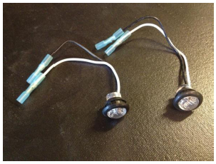
Installing ¾” LED’s on a Jeep JK equipped with MCE Fenders
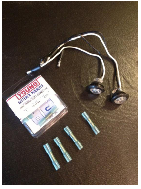
Parts needed:
2- ¾” LED’s with grommets in clear/amber or amber/amber
4- 16ga. to 14ga. Heat shrink butt connectors
1- JK sporting MCE Fenders
1) Install butt connectors on LED’s
2) Open up 5/16” hole on side of grill that is exposed after the MCE Fenders are installed to ¾”. We recommend using a “step” or “vary” bit.
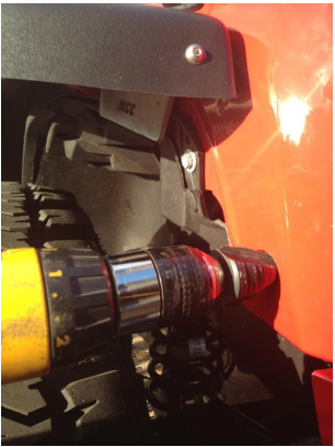
3) Slide grommet off plastic portion of LED. Slide into the 3/4” hole. Push grommet through hole and set it. Then push LED into grommet.
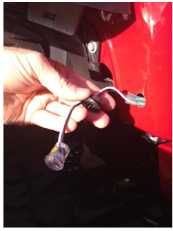
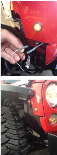
4) Make sure marker light power is off, and cut the two wires that fed the factory marker lights on OEM plastic fenders.
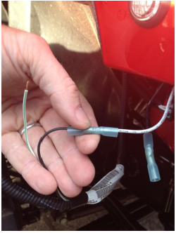
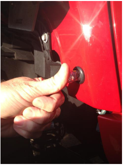
5) Install butt connectors. The LED’s are polarity sensitive (will only light with power going one way). This 2014 JK needed wires to be black/white and white/black for the LED’s to illuminate. Use a lighter to shrink the butt connectors covers. Tuck wires away, and you are complete.