 FREE 1 to 3-Day Delivery on Orders $149+ Details

How to Install DV8 Off-Road Tailgate-Mounted Tire Carrier (18-19 Jeep Wrangler JL) on your Jeep Wrangler
Installation Time
60 minutes
Tools Required
- Trim Removal Tool (plastic or wood to prevent scratches on the paint)
- Hex (Allen) Key (5mm)
- Ratchet (3/8 and 1/2”)
- Sockets (1/2” and 18mm)
- Wrench (18mm)
- Torx (8, 25 and 50)
- Trimming Tool (e.g. Rotary tool with cutting disk)
- Hammer or Rubber Mallet
- Additional Hardware (Not included with the tire carrier): M10x1.5x60 bolts (4), M10 Locking Washers (4), Rubber Washers (optional x 12)

Shop Parts in this Guide
Note: Park the vehicle on a safe and leveled surface and wear protection gear.
Installation Instructions:
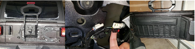
1. Remove the inner cover of the rear door. To do this, pull on the nylon cable cover on the bottom left of the panel. This will help you release the first group of clips. Continue pulling (or using the trim removal tool) remove the remaining clips and put the panel aside.
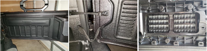
2. Now disconnect the top two cable connectors on the right of the rear door inner panel.
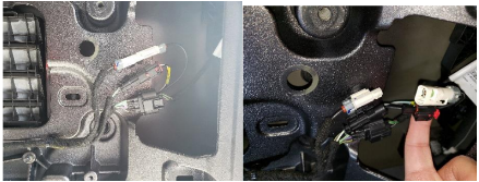
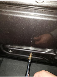
3. Pull the rear-view camera cable plug from the outside and completely remove the cable harness.
4. With the T-25, remove the four bolts holding the third break light bracket (save hardware).
5. With the 1⁄2” socket, remove the eight bolts holding the factory spare tire carrier to the back door (save hardware). Set the factory tire carrier aside.
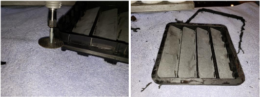
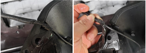
6. Open the rear door and use a trim removal tool to release the two tailgate exhausters.
7. Using the rotary tool and a cutting disk, trim the tailgate exhauster so they are flushed.
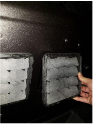
8. Place the tailgate exhausters back on the rear door.
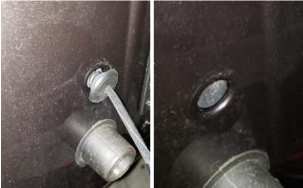
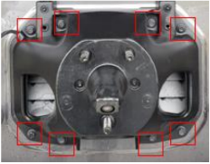
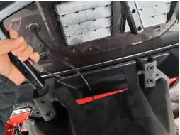
9. With the rear door of the Jeep closed and latched remove the four factory torx bolts using a T-50.
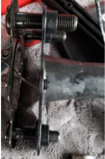
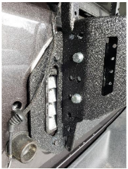
10. Place the carrier’s main reinforcement plate against the door hinges. Place one of the provided spacers between the plate and the hinge. Then one M10X1.5x60 bolt and washer in the hole. Screw loosely until all carrier bolts are attached. In the image below, you will also note the optional rubber washer I opted to use to protect the
paint.
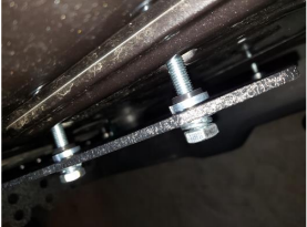
11. Tight all twelve bolts. The four bolts on the hinges will require the M10X1.5x60 bolts while the remaining eight around the tailgate exhausters will reuse the factory hardware.
12. Release the cable harness from the slot on the back of the factory spare tire carrier.
13. Remove the third break light bracket from the factory spare tire carrier.
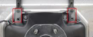
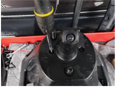
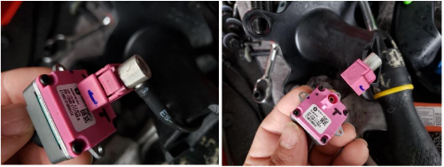
14. Place the factory spare tire carrier on top of a working table and remove the two torx screws holding the camera bracket to the tire carrier using a T-25.
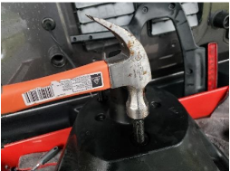
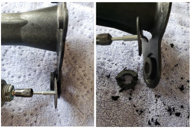
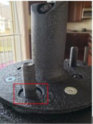
15. Using a hammer or a rubber mallet, hit the spare tire studs until the camera mount and the stud plate are released from the factory spare tire carrier.
16. Remove the clip holding the camera cable to the stud plate.
17. Using a T-8, remove the three screws holding the camera to the factory camera bracket.
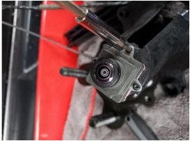
18. Pull the camera out of the bracket and press the tab on the cable connector. Then pull the connector away to release the camera.
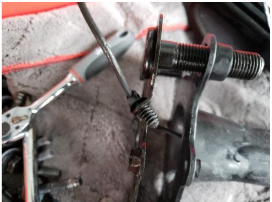
19. Separate the camera mount from the factory stud plate. Try to keep the two parts leveled as you separate them. This will help the studs slide through the camera mount holes with ease.
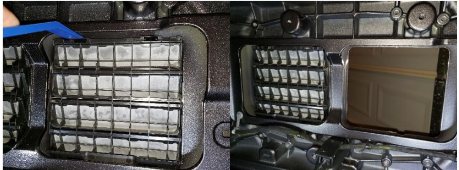
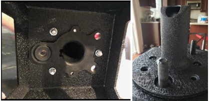
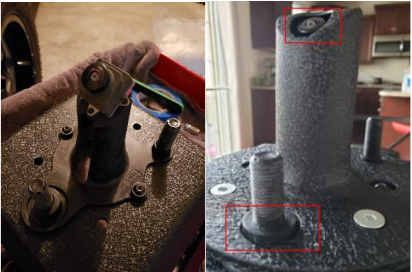
20. According to the manufacturer, the factory camera mount should be inserted from behind the new tire carrier base as shown in the first image below. I noted though, that this result in a recessed camera when all is put together (see second image) which causes a blockage in the peripheral view while in operation. Because of this, I opted to use a different approach to bring the camera forward as described in the following steps. If you opt to follow the manufacturer’s suggestion, simply insert the camera mount as shown in the first picture below, then insert the stud plate and skip to steps 24. Otherwise follow along all the following steps.
21. Place the factory camera mount on top of the new tire carrier base and then insert the new camera housing on top as shown below. You will note that the camera is flushed with the new camera housing. That would prevent the blockage in the peripheral view, but there is a protuberant piece of rubber from the factory camera mount that would prevent full contact with the wheel and the metal base.
22. To fix this, use the rotary tool with and the cutting disk and remove the excess material from the three stud holes in the factory camera mount.
23. Insert the stud plate in the new tire carrier base from behind the base and and pass the camera cable through the base hole.
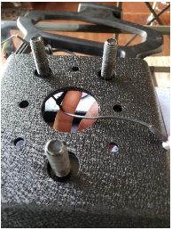
24. Now insert the camera cable through the camera mount and place the camera mount on top of the suds. Connect the camera and install it in its mount using the T-8 and the three factory bolts.
25. Place the new camera housing on top of the base and secure using the provided allen head screws and nuts. Note how the camera mount rubber is no longer preventing the full contact of the base with the wheel.
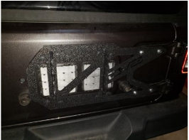
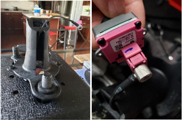
26. Now mount the new tire carrier on main enforcement plate using the provided hardware and tight using a 18mm socket and wrench. Adjust height accoring to your tire size. The height setting shown in the picture below cleared a 35” tire.
27. Reinstall the third brake light factory bracket using the factory hardware and the T-25, insert the camera harness through the hole in the rear door, reconnect the cables and reinstall the door panel.
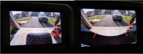
28. Below is a sample image of the rear view camera without the tire and with the tire. Note how there is no loss in periferal view (with the mounting option explained in steps 20-25) when there is no tire. Depending on the offset of your wheels you might still have a loss in periferal view when the wheel is mounted as shown in the second image.
Installation Instructions Written by ExtremeTerrain Customer Duamel Santiago 12/31/2018
