 FREE 1 to 3-Day Delivery on Orders $149+ Details

How to Install Crown Automotive Dana 35 Rear Axle Disc Brake Conversion Kit w/o Parking Brake Cables (97-06 Wrangler TJ w/o ABS) on your Jeep Wrangler

Shop Parts in this Guide
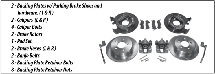
Step 1: Verify that your kit is complete. The kit should include:
Please note: On some vehicles, an aftermarket Brake Proportioning valve may be necessary to ensure the proper amount of hydraulic pressure, front and rear (not included).
On some vehicles with aftermarket wheels, longer wheel studs may be necessary. (Use Replacement part # 4762841, not included)
We recommend that you use a good REPAIR MANUAL to guide you through the more complicated steps of this procedure! (Axle removal, etc.)
Step 2: Jack up the Jeep and support with a set of good jack stands. Make sure to chock both front wheels for safety.
Step 3: Disconnect your existing parking brake cables from the front bracket.
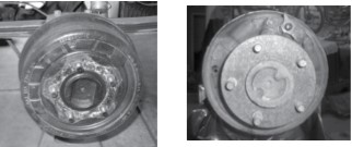
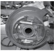
Step 4: Remove the Tires and Brake Drums. In some cases the drums may be difficult to remove if the shoes are too tight. You can locate the rubber plug on the backing plate, remove it, and loosen your adjuster with a flat screwdriver.
Step 5: Disconnect the Brake Lines from the Wheel Cylinders from behind the existing backing plates.
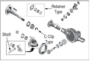
Step 6: (For vehicles with C- Clip Differentials) Depending on your Jeep type, this would be for Jeeps after approximately 1990. Remove the Differential Cover. Unbolt and remove the differential shaft. Pull the C-clip off to allow axle removal.
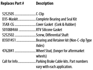
This is a good time to inspect your differential for metal shavings, wear, etc. Inspect your bearings and seals. If necessary, the following components are available from your CROWN Dealer:
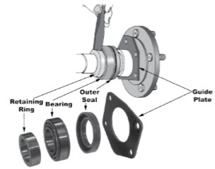
Step 7: ( For vehicles without C-Clip Differentials, approximately 1989 and prior.) Remove the outer retainer. Remove the axle. Press or cut off the existing Bearing, Retaining Ring and Seal.
Step 8: Remove the old Backing Plate assembly, including Shoes.
Wheel Cylinders, etc. Clean and inspect the Bearing surfaces.
Step 9: Remove the Backing Plate Studs and Nuts. Replace these with the new hardware included. Attach the new left and right Backing Plate Assemblies. (Please note that the Left (Driver’s side) is labeled “L” and the Right (Passenger Side) is labeled “R”.)
Step 10: Check to see that the new Brake Rotors fit correctly over the new Shoes. If not, move the adjuster until the Rotors just fit past the Shoes.
Step 11: (For non C- Clip Applications) Replace the Retainer Plate and Spacers. We recommend that you purchase 2 (Replaces Part # 83501451) Bearing Kits prior to this step. The kit includes the Bearing, Seal, Retainer Plate and Retainer Ring (Pre-load Spacer).
Step 12: Prepare your Axles for reinstallation. We highly recommend that you follow a good repair manual for instructions, in order to make sure that you properly grease the Axles and Seals, as well as pressing the Bearings and retainers in place.
Step 13 (For vehicles without C-Clip Differentials) Slide the axles into the Tube assembly most of the way. Grease the seal, and place the spacer over the seal. Carefully slide the axle in all the way, making sure that the splines line up in the differential correctly. Take care to not damage the Bearings and Seals during this process. Tighten the retainer nuts to 32 ft. lbs.
Step 14 (For vehicles with C-Clip Differentials) Carefully slide the Axles completely into the housing, lining the splines up correctly in the Differential Side Gears. Attach the axle with the C-clip. Seat the C-clips by forcing the Axle outward. Reinstall the differential shaft (tighten the locking pin on the shaft to 14 ft. lbs.) If the locking pin is worn or damaged, make sure that you replace it before proceeding further. Turn the axles and make sure that the Differential is fitted correctly.
Step 15 Clean the Differential Cover mating surfaces. You can choose RTV Silicone or Gasket # 35AX-CG to install the Differential Cover. Tighten the cover bolts to 35 ft. lbs. Fill with Differential Fluid. For “TracLoc” applications, add Limited Slip Additive (4318060R)
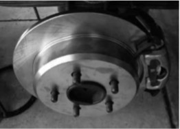
Step 16 Slide the new Brake Rotors into place.
Step 17: Insert the Inner Brake Pads into the Caliper Piston and press by hand into place. Press the Outer Brake pads over the ears of the Calipers. Make sure that the Pad is properly seated.
Step 18: Place the assembled Caliper into position and bolt in place on the mounting plate. (torque to 11 ft. lbs.) WARNING! Take care to not over tighten!
Step 19: Attach the two new Brake Hoses to the existing steel brake lines. The brackets on the hoses are marked L & R. Attach the square end of the Brake Hoses to the Calipers, making sure that a copper washer is placed on either side of the Banjo Bolts. (torque to 23 ft. lbs)
Step 20: Bleed the brakes. Refer to a good manual for instructions. Check Brake operation carefully before driving in traffic! Inspect for leaks. Verify that the Brake Rotors rotate freely
Step 21: Attach a new set of Parking Brake Cables to the lever on the back of each Backing Plate. (not included)
Step 22: Replace the Wheels and lower the vehicle.
Step 23: Attach the front end of the two Brake Cables to the front bracket & equalizer. Reattach all chassis retainer clips.
Step 24: Once again verify that the Brake Rotors rotate freely. Fully engage the Parking Brake Lever. Jack up the end of the vehicle and secure with the jack stands and front wheel chocks.
Step 25: Mark the tensioner rod about ¼” from the tensioner bracket. Tighten the adjusting nut at the equalizer until the mark on the tensioner rod lines up with the tensioner bracket. Release the Parking Brake Lever and check once again to see that the rear wheels move freely. Lower the vehicle.
Step 26: Test the Parking brake on an incline, idling in low gear. Re-inspect the hydraulics and test again by applying pressure before driving on public roadways.

