 FREE 1 to 3-Day Delivery on Orders $149+ Details

How to Install Complete OEM Exhaust Kit (97-99 4.0L Jeep Wrangler TJ) on your Jeep Wrangler
Installation Time
2 hours
Tools Required
- Socket Wrench
- 14mm Socket
- 14mm Combination Wrench
- Torque Wrench
- Flathead Screwdriver or Channel Lock Pliers
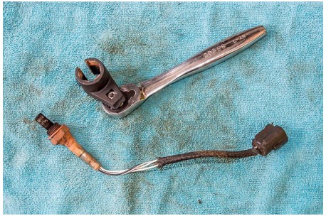
- Special Socket for Oxygen Sensor Installation and Removal
- Rubber Mallet
- Reciprocating saw or comparable cutting tool to remove old system
- Gloves to protect hands
- Safety Glasses to protect eyes from falling rust and debris
It is helpful to have an assistant to help with this installation.
The vehicle on which this system was installed for this guide was a 1997 Jeep Wrangler TJ with a 2.5” suspension lift and 32” tires so I did not have to lift the vehicle with a jack and stands; however, you may find that your particular installation will go smoother if you use a floor jack and jack stands to give yourself more working room.
The vehicle should be parked on a level surface, turned off, and allowed to cool fully as you will be handling exhaust components; ensure that you set the parking brake with the vehicle transmission in park (mine is an automatic).
If you choose to use a jack, make certain that you properly lift the vehicle and fully support its weight with jack stands of the appropriate rating. Use caution working underneath a vehicle supported on jack stands.
Eye protection should be worn to prevent rust, dirt and metal debris from falling into your eyes. Gloves will also protect your hands from injury during the installation.
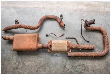
It should be noted that my particular installation was on a 1997 Jeep TJ 4.0L that has been in the process of a restoration and had been sitting up for quite some time. Rust was everywhere, bolts were difficult to remove, and I needed to replace both (only two on 1997 TJ 4.0) oxygen sensors.
I used a spray penetrating oil on all fasteners and hangers several days before the installation to ease removal. I also opted to cut the old system into three pieces for removal as opposed to lowering my transfer skid.
You may need to purchase other items prior to installation as I did to include cable ties, two rubber exhaust hangers, dielectric grease for the oxygen sensor electrical connectors, a can of silicon spray, copper anti-seize compound (if not already on oxygen sensors), upstream oxygen sensor, and downstream oxygen sensor.
I also purchased extra 2 ¼” heavy duty muffler clamps as my kit only had one muffler clamp, and I did not notice this until ready to install.
Installation Instructions:
1. Park on a level surface.
2. Set parking brake and chock wheels.
3. Allow vehicle to fully cool.
4. Put on eye protection.
5. Disconnect battery.
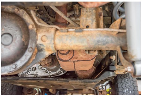
6. Inspect the current exhaust system.
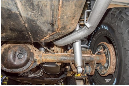
7. On the 1997 TJ 4.0L, the exhaust is mounted to the vehicle in four places.
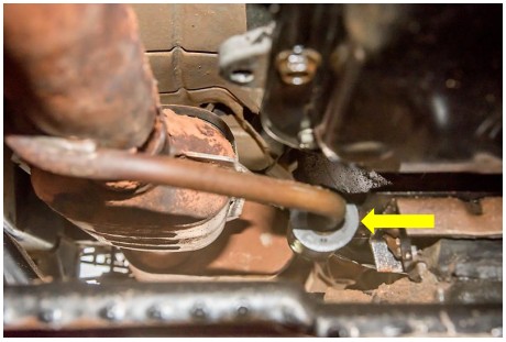
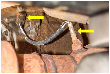
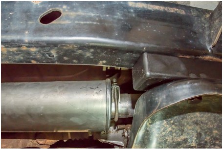
8. Note the two rubber exhaust hangers, one on either side of the rear axle.
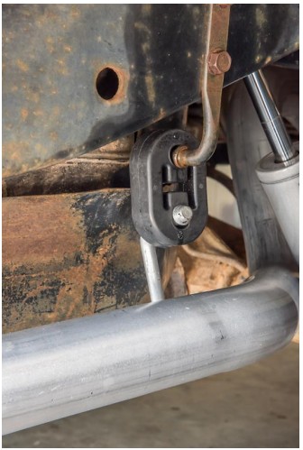
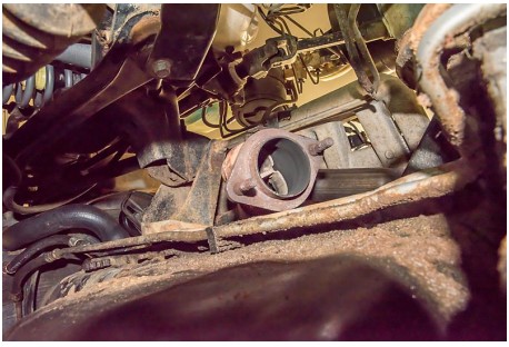
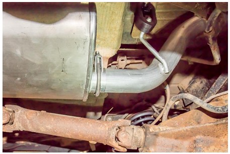
9. Note the rubber isolator mount into which the rod just forward of the catalytic converter slips.
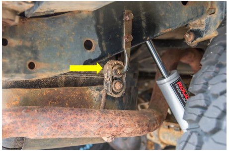
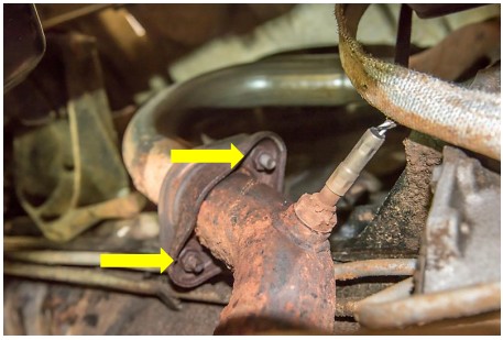
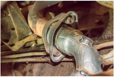
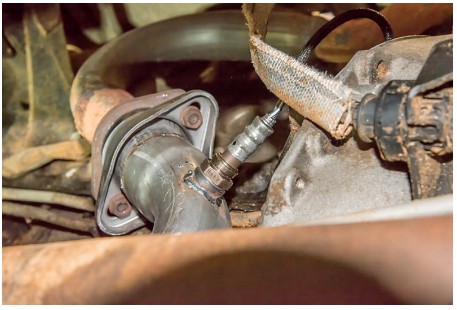
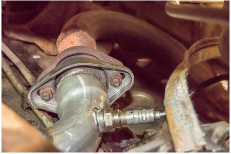
10. Note the flange up front where the down pipe mates to the header, and is held in place by two 14mm nuts.
11. Locate oxygen sensors; note how the electrical connectors are routed/attached to the vehicle.
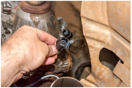
12. Disconnect the electrical connectors before exhaust system removal. There is a locking tab that you lift up before sliding the connector apart.
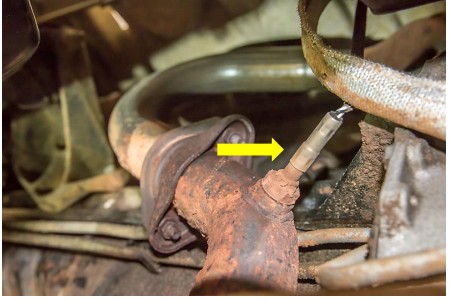
13. The 1997 TJ 4.0L depicted here has one upstream oxygen sensor in the down pipe just below the header flange, and a downstream oxygen sensor in the edge of the catalytic converter.
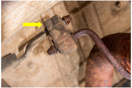
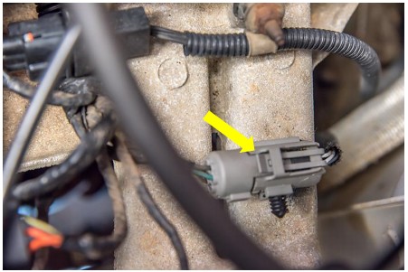
14. The upstream oxygen sensor’s electrical wires run up the firewall behind the engine and terminate in a graycylindrical connector on the manifold.
15. The downstream oxygen sensor’s electrical wires run up to the top of the transfer case, and terminate in a black electrical connector clipped to a tab on the top of the transfer case.
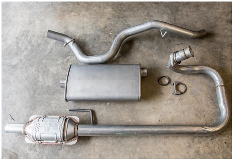
16. The new exhaust system has a tailpipe assembly with two pre-welded hanger rods, a muffler with two 2 ¼” clamps, a down pipe assembly with flange and catalytic converter that has the hanger rod welded into place, and a tapered gasket for the downpipe flange/header.
17. Remove the current exhaust system from the rear to the front of the vehicle.
18. Remove the rubber exhaust hangers by spraying with silicon spray and using a flathead screwdriver or channel lock pliers.
19. I then used the oxygen sensor socket to remove the downstream oxygen sensor; this was mostly out of curiosity as I wanted to see just how much carbon was built up on the sensor.
20. Use a socket wrench and a 14mm socket to carefully remove the two nuts that secure the header flange to the down pipe assembly.
21. A very slight tap with a rubber mallet will release the system from the flange; be careful using too much force here.
22. I chose to use a reciprocating saw to cut the system into three pieces for removal. I cut the exhaust pipe just behind the muffler and just before the catalytic converter.
23. Carefully remove the pieces.
24. Carefully work the tail pipe assembly into place over the axle housing.
25. Use a small amount of silicon spray on the rubber hanger to help push it over the hanger rods into place.
26. Mount only the rear most hanger so that there will be free play to mount the muffler in a future step.
27. Remove the original bushing that was on the header flange with a flathead screwdriver and pliers.
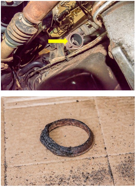
28. Install the new bushing supplied in the Crown kit with the thick side against the header flange and the tapered end facing away from the header.
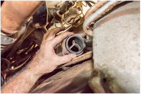
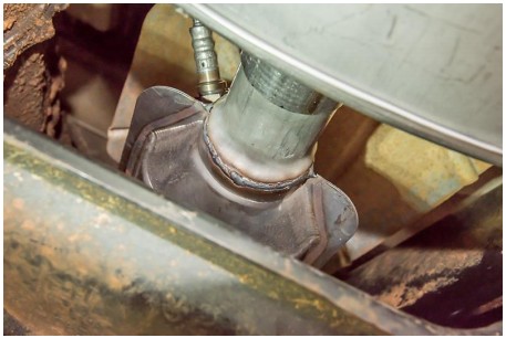
29. Position the new downpipe and catalytic converter assembly into place.
30. Slide the rod mounted near the converter into the rubber isolator from the front.
31. Loosely fasten the nuts on the header flange to allow movement in the system.
32. You may need to support the pipe just in front of the oil pan with a jack stand.
33. Install the new oxygen sensors; follow the instructions with the oxygen sensors, particularly the cautions on handling them and torque specifications.
34. Ensure you have the correct part numbers as the upstream and downstream sensors are different!
35. Apply a light coat of anti-seize compound to threads of oxygen sensors if not already coated from manufacturer.
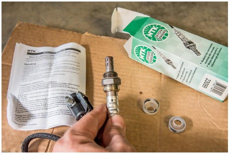
36. Install the upstream and downstream sensors by carefully hand tightening them in their appropriate locations.
37. Torque them to 30 ft. lbs. per the manufacturer’s guidelines of 26 to 33 ft. lbs. in the instruction guide (for my 1997 TJ 4.0L).
38. Use caution not to twist the wiring when installing the new sensors.
39. Route new wiring harnesses.
40. Apply dielectric grease on the connectors before fastening them in place
41. Slide the muffler onto the pipe exiting the catalytic converter; it is a tight slip/friction fit.
42. Slide the tailpipe into the muffler; it is also a tight slip/friction fit.
43. Attach the muffler side rubber hanger at this time; use silicon spray to ease attachment.
44. Ensure approximately 1” to 2” of clearance between all exhaust system components and anything else under the body; keep in mind that exhaust components get hot and can start a fire!
45. Tighten the two 14mm nuts on the header flange. The proper torque setting for my 1997 Jeep TJ was 23 ft. lbs.
for these nuts; however, I could not get my torque wrench into the confined space so I securely tightened them.
46. Ensure that the bushing is centered as you tighten.
47. Position one 2 ¼” muffler clamp over the joint between the muffler and pipe on the catalytic converter side; the saddle and nuts should rest on top of the pipe.
48. Tighten snugly; you do not want to tighten so much that you damage the pipe! I positioned the clamp in such a location to allow a muffler shop to weld around the joint for extra security in the future.
49. Position the second 2 ¼” muffler clamp over the joint between the muffler and pipe on the exit side; the saddle and nuts should rest on top of the pipe.
50. Tighten snugly; you do not want to tighten so much that you damage the pipe! I positioned the clamp in such a location to allow a muffler shop to weld around the joint for extra security in the future.
51. Ensure rubber exhaust hanger is secure when you finish.
52. Double check header flange bolts for tightness.
53. Check both 2 ¼” muffler clamps for tightness.
54. Check both rubber exhaust hangers and ensure they are secure.
55. Check both oxygen sensors for tightness.
56. Check oxygen sensor wiring.
57. Use cable ties to tie up sensor wires to protect them from heat or abrasion.
58. Ensure all connectors are securely fastened.
59. Finally, double check clearance of the entire system in relation to engine and body components; ensure at least 1” to 2” of clearance all the way around the exhaust system for protection from fire and damage.
60. Remove any stands or supports which you have in place and lower vehicle if applicable.
61. Reconnect battery.
62. Start vehicle and allow to run. You should not hear any exhaust leaks, and you should not see any engine codes if you installed properly.
Installation instructions written by ExtremeTerrain customer John Dixon 07/13/2019
