FREE 1 to 3-Day Delivery on Orders $149+ Details

How to Install Bushwacker Pocket Flares on your 07-18 Jeep Wrangler JK
Tools Required
- Pro Tool/Trim Tool
- Flat Head Screwdriver
- 10mm Socket
- Electric Drill
- 5/16" Drill Bit
- Soft Wiping Cloth
- Isopropyl Alcohol
- Grease Pencil
- Hack Saw
- #2 Phillips Screwdriver
- Masking Tape
- Vise Grips
- Awl
- T-45 Torx Bit & Driver
- Socket Ratchet

Shop Parts in this Guide
Step 1 - Prior to Installation
A) Bushwacker only approves installing the fl ares according to these written instructions with the hardware provided. WARNING: Failure to install according to these instructions will invalidate the warranty. This includes, but is not limited to using alternative installation methods, hardware, or materials. DO NOT USE: Loctite, SuperGlue, or similar products on the hardware or the flares.
B) Fit: Verify the fit of the flares to vehicle. (Some filing, sanding, or cutting may be necessary to ensure proper fit).
C) Painting: (Optional) if paint is desired it must be done prior to installing flares on vehicle. Clean outer surface with a good grade degreaser. DO NOT USE LACQUER THINNER OR ENAMEL REDUCER AS A DEGREASER. Wipe outer surface thoroughly with a tack rag prior to paint. Application of plastic adhesion promoter for ABS plastic as per your paint system manufacturer’s recommendations is required. Paint flares using a high quality enamel, or polyurethane automotive paint. If painting edge trim (not recommended), use a flex additive.
D) Performance: Using larger Tires may increase the area required to turn the vehicle. Some Tire/Rim combinations may require lowering bump stops and or installing steering stops to prevent tire from contacting flare.
E) Exhaust System: Modifi cations may be necessary to maintain a minimum 4” clearance between flares and exhaust pipes. (Exhaust gases should not vent directly onto flares)
F) Metal Protection: All exposed fasteners and bare metal should be treated with rust resistant paint BEFORE installing flares. Spray inner fender wells with undercoating AFTER flare attachments have been completed.
G) Decals: Flares may interfere with existing decals on vehicle. If you wish, remove decals prior to installation of flares.
H) Care & Cleaning: Bushwacker fender flares are built to last; any detergent you use to wash your vehicle is suffi cient to clean the flare. Do not use any harsh abrasive detergents.
NOTE: These instructions involve cutting parts of the vehicle. It is important to read all instructions prior to cutting and installing of flares.
PLEASE READ: Dirt and debris can become lodged between the fender fl ares and the vehicle’s fenders, causing scratching and paint wear from vibration. Lund International is not responsible for any damage, and the installation of our fender fl ares is done with the buyer’s understanding that this scratching and paint wear may occur.
LIMITED LIFETIME WARRANTY AGAINST ANY MANUFACTURING DEFECTS
To claim a warranty, you must provide Proof of Purchase.
Step 2 - Edge Trim Installation
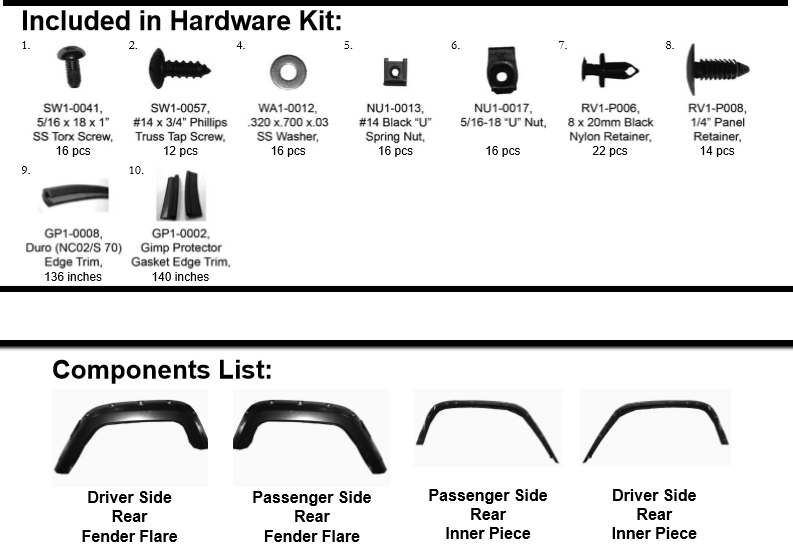
NOTE: Edge trim (GP1-0008) will be installed on the FLARES only, not the inner pieces.
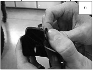
A. Peel two to three inches of red vinyl backing away from Edge Trim (GP1-0008) tape. Applying the adhesive side of the edge trim to the inner side of the flare, affix the edge trim to the top edge of the flare (the portion that comes in contact with the vehicle).
B. Press edge trim into place along the top edge of the flare in one-foot increments, pulling red vinyl backing free as you continue to work your way around the top edge of the flare.
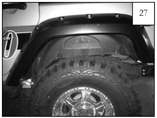
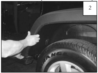
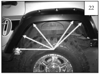
Rear Factory Flare Removal Procedures (Driver's Side)
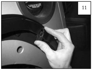
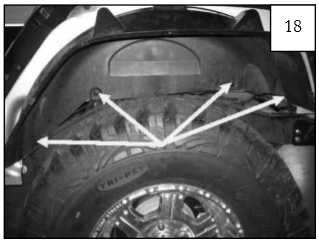
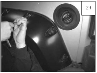
Using a pry tool, pliers, or a flat head screwdriver, remove six plastic fasteners from inside of splash shield.
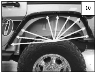
Starting at front of flare, pull firmly to release flare and splash shield from fender, working your way to the back. You will hear popping noises as clips release. It is okay if clips break, they will be discarded.
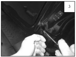
Using a pry tool or flat head screwdriver, remove any plastic clips that have remained in fender.
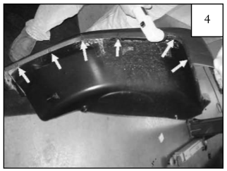
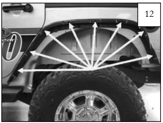
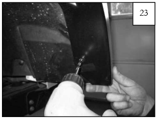
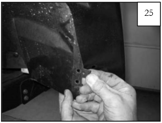
Use a drill with a 5/16” bit to drill through six plastic rivets along edge of fl are/splash shield. Discard the flare, but retain the splash shield. NOTE: It is helpful to angle the drill while drilling the rivets.
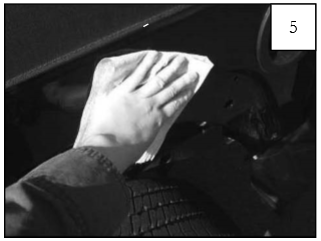
Rear Flare Installation Procedures (Driver's Side)
Clean fender area thoroughly with a soft clean cloth.
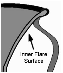
Make sure gimp (GP1-0002) and inner flare are clean. Peel 2” of liner from gimp (pin shape). Carefully position gimp as uniformly as possible along radius as shown, peeling liner as you go. Gimp can be repositioned as needed. NOTE: It is better for gimp to be slightly below radius rather than above.
When positioning gimp (GP1-0002) on narrow end of rear, fold flat edge of gimp over the edge of the part. (Gimp will continue over entire length of part.)
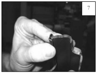
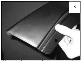
After gimp is properly placed, press to adhere properly and cut ends flush with ends of inner flare.
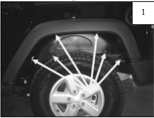
Position Inner Flare Piece on fender, aligning existing 5/16” holes in Inner Flare Piece with holes in fender. Install supplied Plastic Push Retainers (RV1-P006) (9 places).
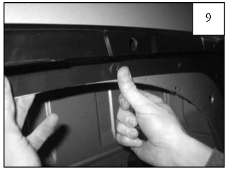
Push Retainer locations.
Install supplied Threaded Clips (NU1-0017), with the thread side in, over holes in Inner Flare Piece (8 places).
Threaded Clip locations.
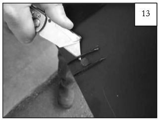
On backside of splash shield, use a utility knife to trim two plastic ribs flush with splash shield surface.
Use a flat head screwdriver to spread supplied #14 U-Clips (NU1-0013) for ease of installation.
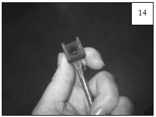
Install supplied #14 U-Clips (NU1-0013) over existing holes in splash shield (5 places). Flat side will be visible once splash shield is reinstalled.
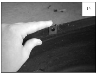
#14 U-Clip locations. NOTE: The rearmost hole will NOT have a clip.
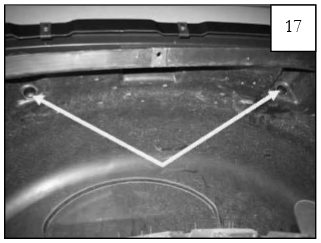
Position splash shield in wheel well, and install two supplied Panel Retainers (RV1-P008) in upper pockets using a pushing-twisting motion.
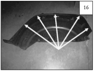
Install four supplied Panel Retainers (RV1-P008) through splash shield and into vehicle body as shown.
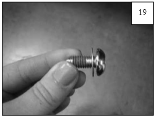
Position Rear Flare over Inner Flare Piece. Slide a supplied .700” Washer (WA1-0012) onto a supplied Torx Screw (SW1-0041).
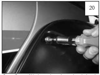
Start Screws/Washers through pocket holes in fl are and into Threaded Clips installed in Step 11 (8 places) starting at the front and working your way to the back. DO NOT TIGHTEN.
Install supplied Truss Head Screws (SW1-0057) through holes in wheel well and into #14 U-Clips installed in Step 15 (5 places).
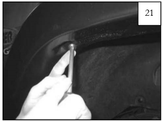
Truss Head Screw Locations.
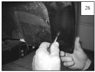
Holding the splash shield firmly, drill through rearmost hole in flare and through the splash shield using a 5/16” bit.
Remove three rear most screws installed in Step 20.
Pull the splash shield out from behind fl are and install a supplied #14 U-Clip over hole drilled in Step 23. This hole will be located slightly above existing hole in splash shield.
Replace splash shield, and install a supplied Truss Head Screw (SW1-0057) through rearmost hole in fl are and into clip installed in Step 25. Reinstall three pocket screws removed in Step 24.
Ensure fit, and tighten all screws.