FREE 1 to 3-Day Delivery on Orders $149+ Details

How to Install Bushwacker Flat Style Fender Flares (07-17 Wrangler JK) on your Jeep Wrangler
Tools Required
- Utility Knife
- Pneumatic Hand Saw or Metal Hacksaw (optional, Step 12)
- #2 Phillips Drive Bit
- Electric Drill
- 5/16” Drill Bit
- #2 Phillips Screwdriver
- Socket Wrench
- 1/2”, 11/32”, & 10mm Sockets
- 1/2” Wrench
- 8” Socket Extension
- Needle Nose Pliers or Vise Grips
- Scratch Awl (optional Step 44)
- Wire Cutter & Stripper
- 22-18 Gauge Wire Crimp
- Soft Wiping Cloth/Shop Towels
- Heat Gun
- Pry bar/Claw Hammer
- Grease Pencil

Shop Parts in this Guide
STEP 1 – PRIOR TO INSTALLATION
A) Bushwacker only approves installing the flares according to these written instructions with the hardware provided. WARNING: Failure to install according to these instructions will invalidate the warranty. This includes, but is not limited to using alternative installation methods, hardware, or materials. DO NOT USE: Loctite, SuperGlue, or similar products on the hardware or the flares.
B) Fit: Verify the fit of the flares to vehicle. (Some filing, sanding, or cutting may be necessary to ensure proper fit).
C) Painting: (Optional) if paint is desired it must be done prior to installing flares on vehicle. Clean outer surface with a good grade degreaser. DO NOT USE LACQUER THINNER OR ENAMEL REDUCER AS A DEGREASER. Wipe outer surface thoroughly with a tack rag prior to paint. Application of plastic adhesion promoter for ABS plastic as per your paint system manufacturer’s recommendations is required. Paint flares using a high quality enamel, or polyurethane automotive paint. If painting edge trim (not recommended), use a flex additive.
D) Performance: Using larger Tires may increase the area required to turn the vehicle. Some Tire/Rim combinations may require lowering bump stops and or installing steering stops to prevent tire from contacting flare.
E) Exhaust System: Modifications may be necessary to maintain a minimum 4” clearance between flares and exhaust pipes. (Exhaust gases should not vent directly onto flares)
F) Metal Protection: All exposed fasteners and bare metal should be treated with rust resistant paint BEFORE installing flares. Spray inner fender wells with undercoating AFTER flare attachments have been completed.
G) Decals: Flares may interfere with existing decals on vehicle. If you wish, remove decals prior to installation of flares.
H) Care & Cleaning: Bushwacker fender flares are built to last; any detergent you use to wash your vehicle is sufficient to clean the flare. Do not use any harsh abrasive detergents.
PLEASE READ: Dirt and debris can become lodged between the fender flares and the vehicle’s fenders, causing scratching and paint wear from vibration. Lund International is not responsible for any damage, and the installation of our fender flares is done with the buyer’s understanding that this scratching and paint wear may occur.
Included in Hardware Kit:
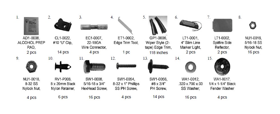
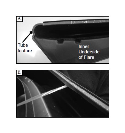
STEP 2 - EDGE TRIM INSTALLATION
The edge trim for this application is double-tape edge trim so special care needs to be taken while installing. There is red vinyl backing on the inside of the edge trim where it will adhere to the flare and red vinyl backing on the outside where it will adhere to the vehicle. The following steps only concern where the edge trim will adhere to the flare. Additional edge trim installation instructions are included during the rest of the installation process.
A. Peel two to three inches of red vinyl backing away from edge trim tape. Applying the adhesive side of the edge trim to the inner side of the flare, affix the edge trim to the top edge of the flare (the portion that comes in contact with the vehicle). Stop at tube feature of flare. Picture A for tube feature reference
B. Press edge trim into place along the top edge of the flare in one-foot increments, pulling red vinyl backing free as you continue to work your way around the top edge of the flare. See Picture B for additional edge trim orientation
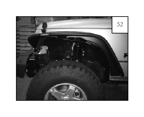
Front Flare Installation Procedures (Driver’s Side):
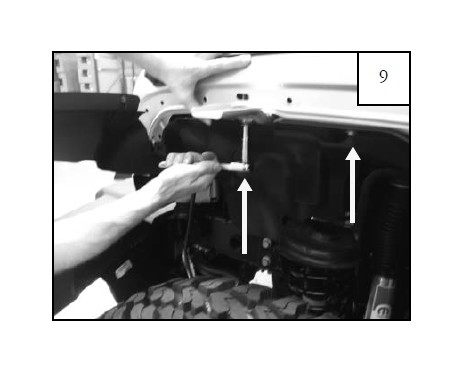
Using a socket wrench with a 10mm socket, remove four factory bolts from inside of splash shield. Save bolts for reinstallation.
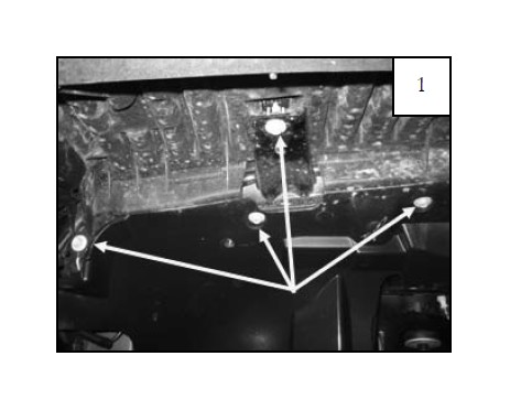
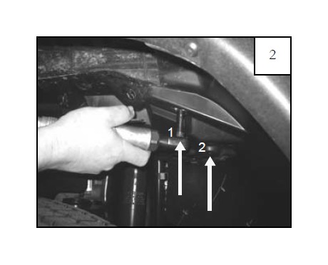
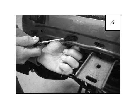
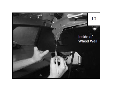
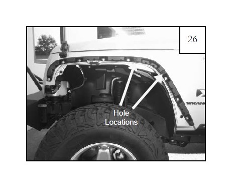
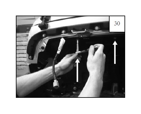
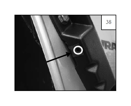
Using a socket wrench with a 10mm socket, remove bolt located in hole inside of splash shield (location 1) and bolt in location 2. Save fasteners for reinstallation. Note: 2007-2010 model years have a plastic thread engager in location 2. Remove and save for reinstallation.
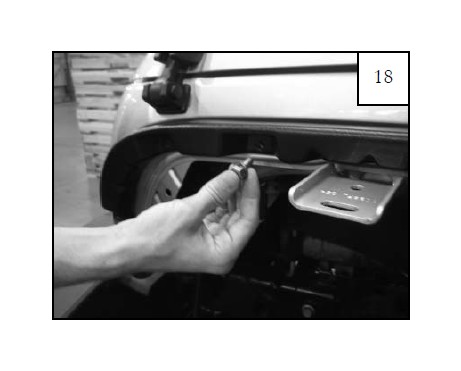
Remove light receptacle from light lens housing, letting it hang free of the housing.
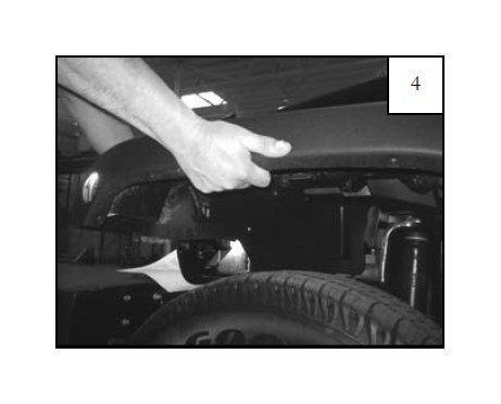
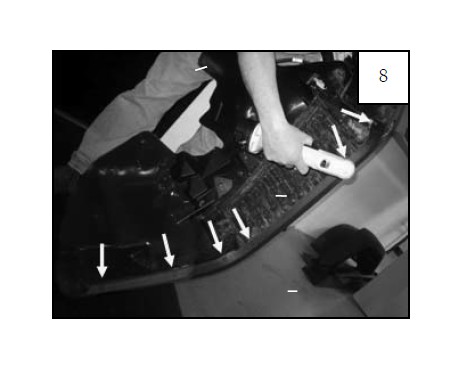
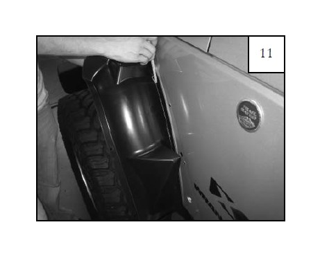
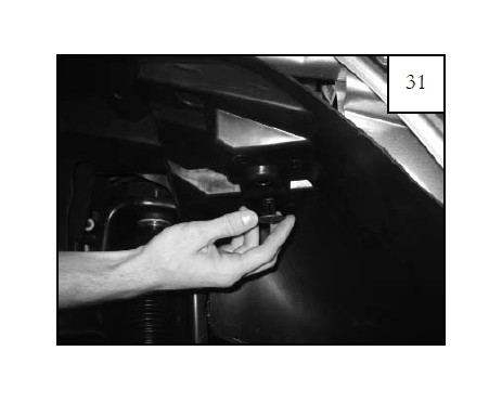
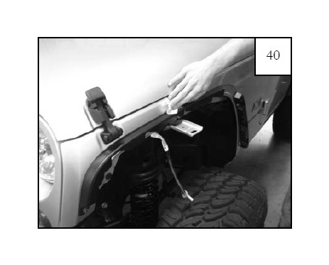
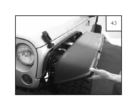
Starting at front of flare, pull firmly to release flare and splash shield from fender, working your way to the back. You will hear popping noises as clips release. It is okay. If clips break, they will be discarded.
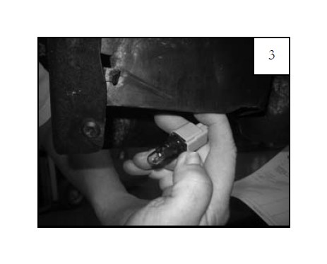
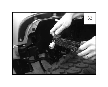
Once flare is free of fender, disconnect light connector. This will allow the flare to come away from fender completely. Save connector for reinstallation.
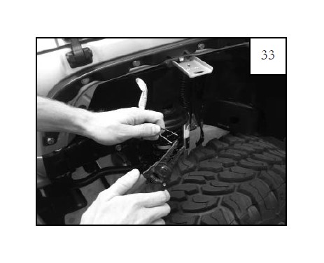
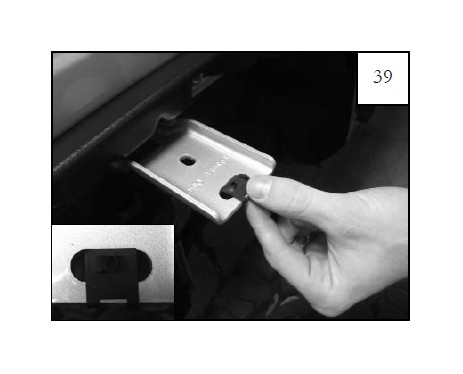
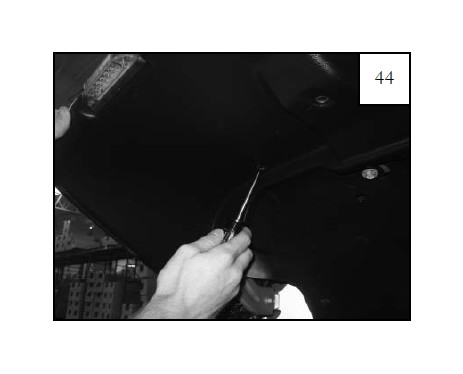
Using a pry tool or flat head screwdriver, remove any plastic clips still in fender.
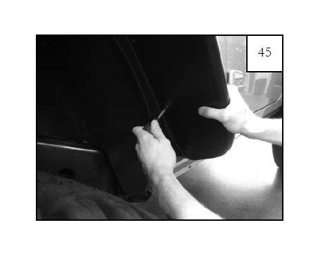
Use a pry tool or flat head screwdriver to remove four plastic fasteners.
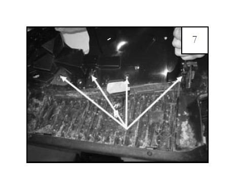
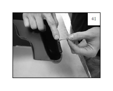
Use a drill with 5/16” bit to drill through six plastic rivets along edge of flare/splash shield. Discard flare. Save splash shield for reinstallation.
Reinstall the splash shield, in preparation for marking before cutting, using supplied 1.25” Washer on factory bolt/washer assembly and reinstall through factory threads in sheet metal (2 locations).
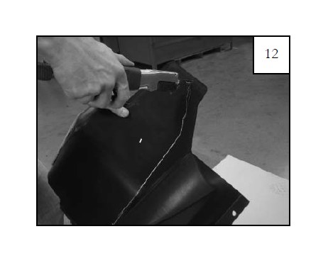
Mark the front portion of the splash shield with a grease pencil in location shown in preparation for trimming. The splash shield should be flush with the sheet metal after being trimmed. NOTE: If trimmed too little, flare won’t fit; if trimmed to much, shield won’t stay behind flare.
Using sheet metal as guide, mark the rear portion of the splash shield with a grease pencil in preparation for trimming. The splash shield should be flush with the sheet metal after being trimmed. NOTE: If trimmed too little, flare won’t fit; if trimmed to much, shield won’t stay behind flare.
Remove splash shield. Save factory hardware for reinstallation. Using a metal hacksaw, pneumatic hand saw, or other suitable cutting device, trim the splash shield along the marked lines.
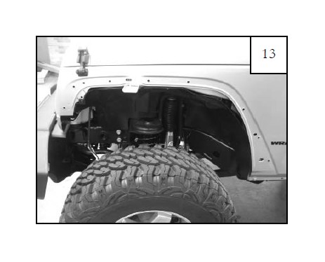
Hold splash shield up to inner wheel well to ensure that the edge is flush with the sheet metal. Remove from wheel well and trim or sand if splash shield extends beyond the sheet metal.
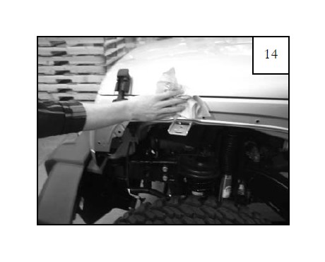
Thoroughly clean the exposed metal fender with a damp cloth and dry.
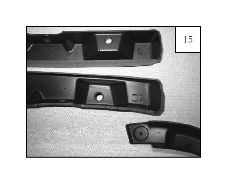
Locate the flat flare front inner pieces. The driver side front inner pieces are marked D1, D2, & D7. The passenger side front inner pieces are marked P1, P2, & P7.
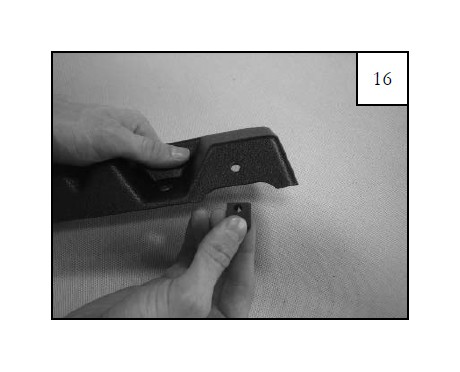
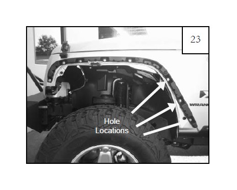
Install a speed clip at each clip location on the inner pieces, centering them on the predrilled holes with threaded portion on inside (6 locations). NOTE: Clips may slide out of place. Try pinching the metal tightly onto the inner piece with pliers.
Secure inner piece D1 (and P1 for passenger side installation) to the sheet metal using the following 4 Steps: Step 1 Position inner piece on fender, aligning with existing factory holes in sheet metal.
Step 2 Slide a .700” Washer onto 5/16” Hex Head Bolt. Insert a bolt/washer assembly through inner flare piece and fender and secure with 5/16” Nylok Nut. Start the bolts but do not tighten.
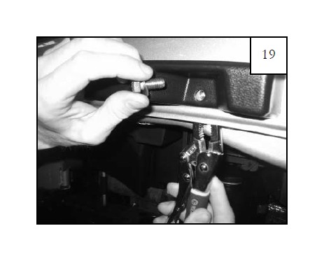
Step 3 For the rearward two mounting locations, use a vice grip to place the Nylok Nut on the back side of the bolt. Start the bolts but do not tighten.
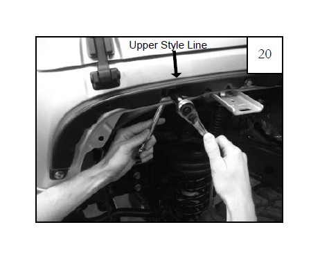
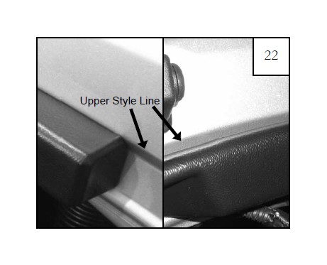
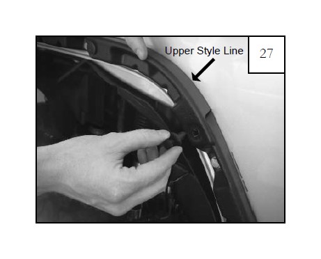
Step 4 Using a 1/2” socket wrench and a 1/2” wrench, tighten all bolts until inner piece is snug against fender and washers do not spin. NOTE: Do not overtighten: See step 21. Inner piece should rest along upper style line of sheet metal radius and not below it: See step 22.
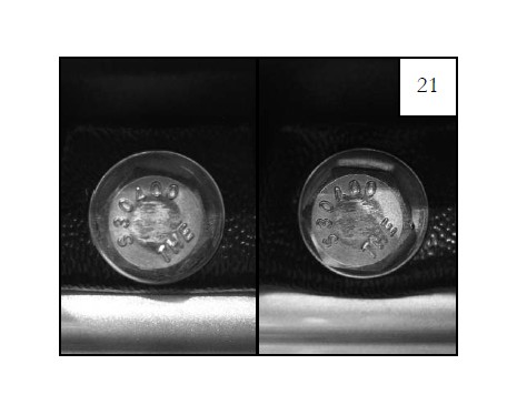
Bolt on left: Properly tightened; lower edge of inner piece runs straight
Bolt on right: Overtightened; lower edge of inner piece bows down; if accidentally overtightened, remove inner piece completely before reinstalling.
Picture on left: Top edge of inner piece along upper style line
Picture on right: Top edge of inner piece tucked below upper style line; this forcibly angles and deforms inner pieces and flare is difficult or impossible to install
Secure inner pieces D2 (and P2 for passenger side installation) to the sheet metal using the following 3 Steps: Step 1 Position inner piece on fender, aligning with existing factory holes in sheet metal.
Step 2 Slide a .700” Washer onto 5/16” Hex Head Bolt. Insert a bolt/washer assembly through inner flare piece and fender and secure with 5/16” Nylok Nut. Start the bolts but do not tighten.
Step 3 Using a 1/2” socket wrench and a 1/2” wrench, tighten all bolts until inner piece is snug against fender. Do not overtighten: see step 21. Inner piece should rest along upper style line of sheet metal radius and not below it: see step 22.
Secure inner pieces D7 (and P7 for passenger side installation) to the sheet metal using the following 2 Steps: Step 1 Position inner piece on fender, aligning with existing holes in first two inner pieces.
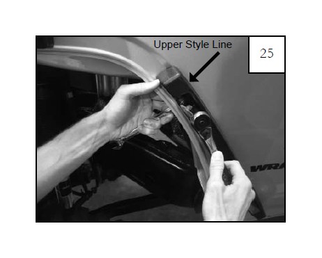
Step 2 While holding the inner piece in place, install a plastic push retainer through holes in both inner pieces. Inner piece should rest along upper style line of sheet metal radius and not below it: see step 22.
Reinstall light connector removed in step 5. Position inner splash shield for reinstallation, making sure that side marker light wires are outside of splash shield.
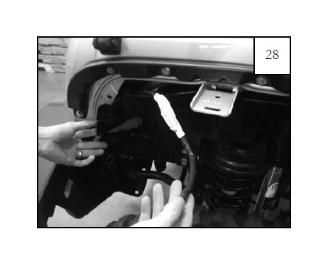
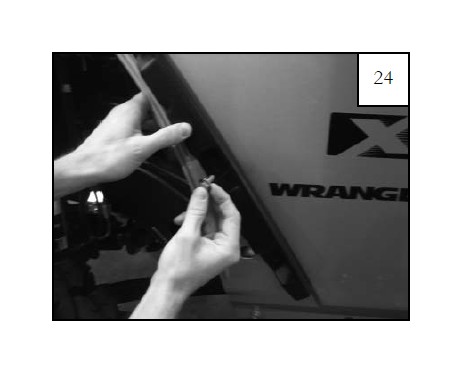
Reinstall inner splash shield by first placing a supplied plastic push retainer through the mounting hole in the sheet metal and splash shield as shown in picture.
Install a supplied 1.25” Washer on factory bolt/ washer assembly and reinstall through factory threads in sheet metal (2 locations).
Reinstall factory fastener removed in Step 2 in location shown. 2007-2010 model years, fastener is a plastic thread engager. 2011-newer model years, fastener is a 10mm bolt.
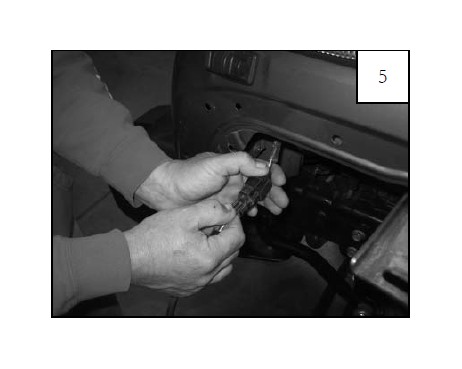
Use wire cutters to cut the two wires at the base of the factory side marker lamp.
Use wire strippers to strip away approximately 3/8” of wire covering from the factory installed side marker lamp wires.
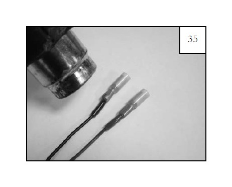
Install a Female Bullet Connector to the end of each factory side marker light wire and secure by pressing firmly with a wire crimp.
Seal heat shrink tubing on wire using a heat gun.
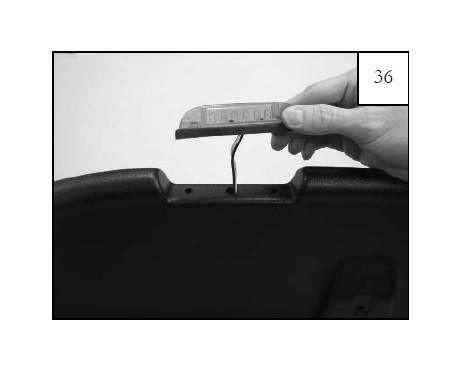
Position the supplied side marker light onto the outer flare piece, threading the wires through the center predrilled hole.
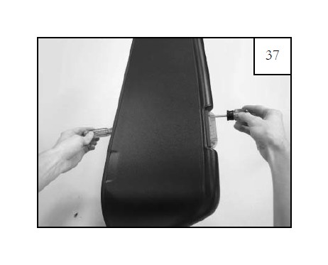
Secure the side marker light to the outer flare with 8-32 screw, 8-32 nut, and washer using a #2 Phillips bit and a 11/32” socket with 8” extension (2 places). NOTE: If you are having trouble putting the washer and nut on the screw, use needle nose pliers.
Before installing the outer flare, make sure that the speed clips on the inner pieces are centered over the predrilled holes.
Before installing the outer flare, install speed clip on metal frame angle support bracket at top center of wheel well. Make sure that it is centered over the factory slot with threaded portion facing up.
Use one supplied alcohol prep pad to clean the sheet metal above each inner piece in preparation to tape the edge trim to the sheet metal. This must be done for proper flare installation.
Peel back 1-2” of red liner on each end of the edge trim and bend toward the outside of the flare.
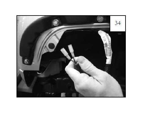
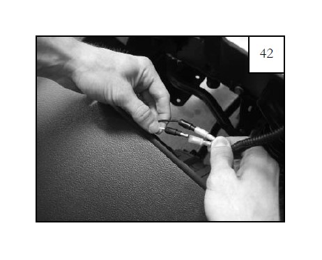
Connect the side marker light wires with the vehicle wires by attaching the male connectors to the female connectors. Test the connection by turning on the front marker/parking lights. Switch connectors if necessary.
Place the outer flare over the inner pieces and push until snug against the sheet metal. Make sure that the side marker light wires are inside the flare. Make sure splash shield is tucked behind flare.
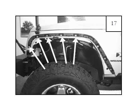
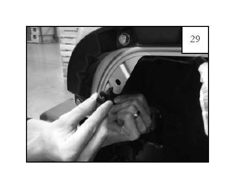
Use a scratch awl (or another pointed tool) to line up the speed clips with the outer flare holes (7 locations). If needed, use a flashlight to better locate the speed clips.
Hold flare in place on fender and start a pan head screw into each hole location and through speed clip on inner structure and metal frame angle support bracket (7 places). Do not tighten.
After all screws have been started, tighten the pan head screws by firmly pressing the flare toward the vehicle while tightening.
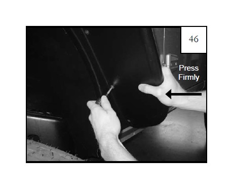
Peel outer tape liner from the double-tape edge trim. Push down lightly on the fender flare to create a small gap between the sheet metal and the edge trim. This makes it easier to pull the red liner.
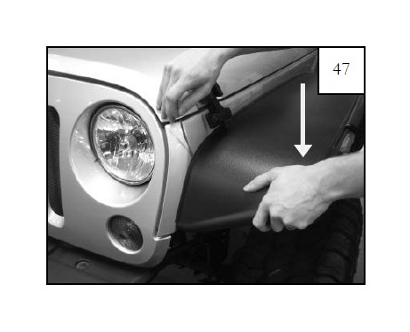
After the red liner is removed, firmly press the flare toward the vehicle for 10 seconds to adhere the tape to the vehicle surface. Repeat this process for the entire length of the flare. The vehicle surface temperature must be between 65-110° F for proper adhesion. Allow 24 hours for full adhesion.
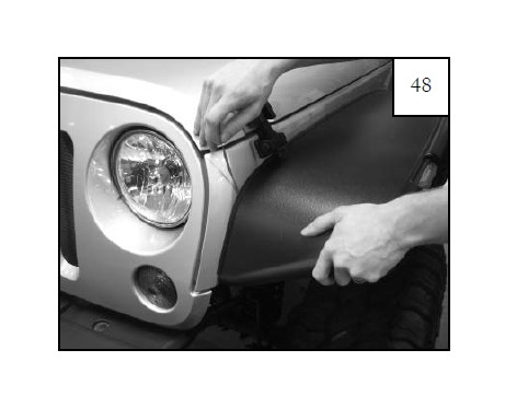
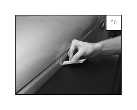
Starting at one end, use the flat edge of the supplied edge trim tool to further adhere the edge trim to the vehicle surface. Slide the tool along the edge trim while pressing it in toward the vehicle surface.
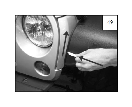
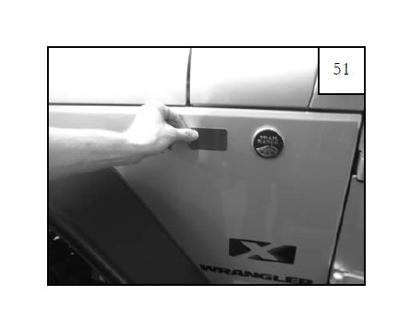
Use the hooked end of the edge trim tool to check for full adhesion. Do this by sliding it along the top of the edge trim to visually verify that the tape is adhered to the vehicle surface. Repeat step 49 if tape is not fully adhered to the vehicle surface.
Attach one side reflex reflector to the side of the vehicle by peeling off the adhesive backing and pressing it firmly onto the cleaned vehicle surface. NOTE: Once reflector has adhered it cannot be repositioned.
Completed front driver’s side flare installation.