 FREE 1 to 3-Day Delivery on Orders $149+ Details

How to Install Bushwacker Factory Width Pocket Style Fender Flares (07-17 Wrangler JK) on your Jeep Wrangler
Tools Required
- Jack & Jack Stands
- Electric Drill
- 11/64” Drill Bit
- 1-1/8” Hole Saw
- Pop Rivet Gun
- Grease Pencil or Marking Pen
- Tape Measure
- Phillips Screw Driver
- Wire Crimper
- Wire Strippers
- Red Oxide Primer

Shop Parts in this Guide
STEP 1 – PRIOR TO INSTALLATION
A) Bushwacker only approves installing the fl ares according to these written instructions with the hardware provided. WARNING: Failure to install according to these instructions will invalidate the warranty. This includes, but is not limited to using alternative installation methods, hardware, or materials. DO NOT USE: Loctite, SuperGlue, or similar products on the hardware or the fl ares.
B) Fit: Verify the fi t of the fl ares to vehicle. (Some fi ling, sanding, or cutting may be necessary to ensure proper fi t).
C) Painting: (Optional) if paint is desired it must be done prior to installing fl ares on vehicle. Clean outer surface with a good grade degreaser. DO NOT USE LACQUER THINNER OR ENAMEL REDUCER AS A DEGREASER. Wipe outer surface thoroughly with a tack rag prior to paint. Application of plastic adhesion promoter for ABS plastic as per your paint system manufacturer’s recommendations is required. Paint fl ares using a high quality enamel, or polyurethane automotive paint. If painting edge trim (not recommended), use a fl ex additive.
D) Performance: Using larger Tires may increase the area required to turn the vehicle. Some Tire/Rim combinations may require lowering bump stops and or installing steering stops to prevent tire from contacting fl are.
E) Exhaust System: Modifi cations may be necessary to maintain a minimum 4” clearance between fl ares and exhaust pipes. (Exhaust gases should not vent directly onto fl ares)
F) Metal Protection: All exposed fasteners and bare metal should be treated with rust resistant paint BEFORE installing fl ares. Spray inner fender wells with undercoating AFTER fl are attachments have been completed.
G) Decals: Flares may interfere with existing decals on vehicle. If you wish, remove decals prior to installation of fl ares.
H) Care & Cleaning: Bushwacker fender fl ares are built to last; any detergent you use to wash your vehicle is suffi cient to clean the fl are. Do not use any harsh abrasive detergents.
PLEASE READ: Dirt and debris can become lodged between the fender fl ares and the vehicle’s fenders, causing scratching and paint wear from vibration. Lund International is not responsible for any damage, and the installation of our fender fl ares is done with the buyer’s understanding that this scratching and paint wear may occur.
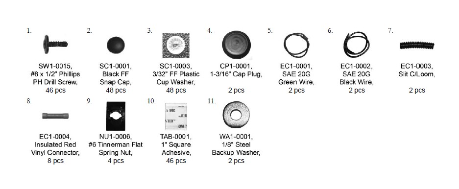
Included in Hardware Kit:
Flare Installation Procedures:
STEP 2 - Edge Trim Installation:
A) Remove factory installed edge trim when necessary.
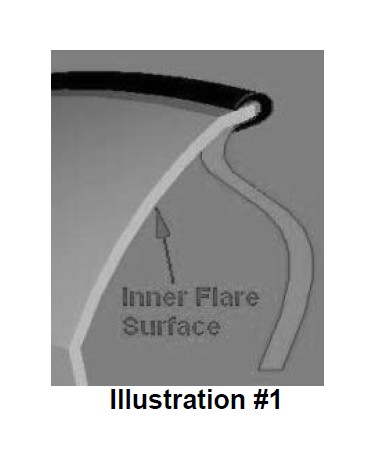
B) Peel two to three inches of red vinyl backing away from edge trim tape. Applying the adhesive side of the edge trim to the inner side of the fl are, affi x the edge trim to the top edge of the fl are (the portion that comes in contact with the vehicle). See Illustration #1
C) Press edge trim into place along the top edge of the fl are in one-foot increments, pulling red vinyl backing free as you continue to work your way around the top edge of the fl are
STEP 3 - Preparing the Work Area (Fronts):
A) Remove tire using jack and jack stands should additional room be required to work in the wheel well area.
B) Remove factory fl ares from all wheel openings.
C) Disconnect signal light bulb assembly from signal light frame and remove frame from fender. Save signal frame for reinstallation.
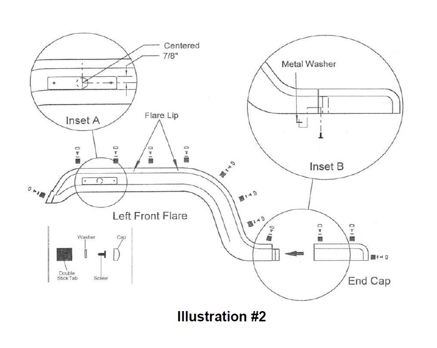
STEP 4 - Flare Installation (Fronts):
Note: Front fl ares are two part construction: the fl are itself and an end cap which covers and extends the lower rear portion of the fl are.
A) Drill twelve 9/64” holes through the fl are and end-cap lip at the locations shown in Illustration #2. Holes should be drilled from the back to avoid marring the outer fl are surface. Screw locations are marked as indents on the lip.
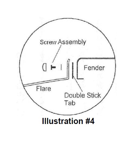
B) Remove one side of the protective paper backing from the double-stick tabs and press onto the inside surface of the lip and over the holes drilled in Step 4A. See Illustration #4.
C) Remove remaining paper backing and press fl are and endcap into position on fender. Shield fl are surface with duct tape or use drill bit extension to prevent marring by drill chuck and drill twelve 9/64” holes in fender through hole drilled in Step 4A.
D) Secure fl are to fender using supplied drill screws through washer. Press caps over washer/screw assemblies. See Illustration #4.
E) Secure the outer edges of fl are and end-cap using a single drill screw. See Illustration #2 – Inset B.
STEP 5 - Marker Light Attachment (Fronts):
A) Center and drill a 1-1/8” hole 7/8” from the top edge and an equal distance from both ends of the light indent. See Illustration #2 – Inset A.
B) Locate and Drill two 11/64” holes by inserting the signal light frame into the 1-1/8” hole, and marking the existing screw positions.
C) Secure signal light frame with supplied fl at nuts over original screws.
D) Lengthen signal light wires to accomodate increased fl are width.
E) Cut original turn signal light wires 4” and 6” from signal bulb and strip all resulting wire ends.
F) Insert four stripped ends into supplied connectors and crimp.
G) Cut extension wire (supplied) into two equal lengths and strip all ends. Insert one extension wire into both vehicle-side connectors and crimp.
H) Cut loom material (supplied) into two equal lengths. Thread vehicle-side wires through a single loom length and butt to existing loom material. Electrical tape can be used to hold old and new loom sections together.
I) Thread loom through original signal light hole; insert vehicleside wire ends into signal-side connectors and crimp.
J) Insert signal bulb assembly into signal frame.
STEP 6 - Flare Installation (Rears):
Note: Rear Flares are of one piece construction and do not require turn signal light remounting.
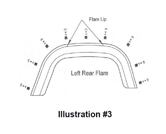
A) Drill twelve 9/64” holes through the fl are at the locations shown in Illustration #3. Holes should be drilled from the back to avoid marring the outer fl are surface. Screw locations are marked as indents on the lip.
B) Remove one side of the protective paper backing from the double-stick tabs and press onto the inside surface of the lip and over the holes drilled in Step 6A. See Illustration #4.
C) Remove remaining paper backing and press fl are and endcap into position on fender. Shield fl are surface with duct tape or use drill bit extension to prevent marring by drill chuck and drill twelve 9/64” holes in fender through hole drilled in Step 6A.
D) Secure fl are to fender using supplied drill screws through washer. Press caps over washer/screw assemblies. See Illustration #4.

