FREE 1 to 3-Day Delivery on Orders $149+ Details

How to Install Baer 14 in. Rear Pro+ Brake Kit (07-18 Wrangler JK) on your Jeep Wrangler

Shop Parts in this Guide
ATTENTION: Read this before going any farther! Returns will not be accepted for ANY installed PART or ASSEMBLY. Use great care to prevent cosmetic damage when performing wheel fit check. In the event that a product must be returned, please contact Baer Customer Service for a RMA Number.
Notices – Read and Follow BEFORE ATTEMPTING INSTALLATION
All installations require proper safety procedures and protective eyewear.
All installations assume basic mechanical skill and a factory service manual for the vehicle on which the installation is to be performed.
All references to the “left” side of the vehicle correlate to the driver’s side of the vehicle.
Any installation requiring you to remove a wheel or gain access under the vehicle requires use of jack stands appropriate to the weight of the vehicle. In all cases, jack stands rated for a minimum of 2-tons is recommended.
A selection of hand tools sufficient to engage in the installation of these products is assumed, and is the responsibility of the installer to have in his/her possession prior to beginning this installation. All installations, which require removal of hydraulic hoses and/or bleeding of the brakes, require appropriate fitting/line wrenches, safety catch can, and protective eyewear. Other than these items, if unique or special tools are required they will be stated appropriately in the installation step.
ALWAYS CONFIRM WHEEL FIT PRIOR TO BEGINNING INSTALLATION OF ANY BRAKE SYSTEM OR “UPSIZED” ROTOR UPGRADE! In addition to checking wheel fitment (available online at www.baer.com), always place the actual corner assembly or a combination of the caliper assembly onto the rotor, and into the actual wheel. This procedure will reconfirm proper clearance between the caliper and the wheel before proceeding with the actual installation.
Returns will not be accepted for systems that have been partially or completely installed. Use extreme care when checking wheel fitment to prevent any cosmetic damage.
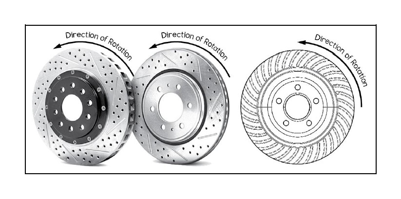
When installing new Baer rotors, be sure to follow the direction of rotation indicated on the rotor hat area with either an arrow, or an “L” for left, or an “R” for right, or both. “L” or left always indicates the driver’s side of US spec vehicles. Images shown are “L” left rotors:
A proper professional wheel alignment is required for any system requiring replacement of the front spindles, or tie rod ends. Follow factory prescribed procedures and specifications unless otherwise indicated.
At any point, stop the installation if anything is unclear, or the parts require force to install. Consult directly with Baer Technical Staff in such instances to confirm details. Please have these instructions, as well as the part number of the component (part numbers are machined into the brackets) that is proving difficult to install, as well as the make, model, and year (date of vehicle production is preferred) of your vehicle available when you call. Baer’s Technical Staff is available from 8:30a.m. - 5:00p.m. Mountain Standard Time (Arizona does not observe Daylight Savings Time) by phone: (602)-233-1411 Monday through Friday.
INSTALLATION:
1. Carefully remove your wheel.
2. Next, unbolt the two OEM caliper bolts securing the caliper in place. Carefully disconnect the brake hose from the hardline and cap the hardline with the supplied vinyl cap. This will prevent brake fluid from dripping onto the components. Set the caliper aside and out of the way.
3. Remove the rotor from the axle and thoroughly clean the mounting face. This will allow the rotor to mount properly once installed.
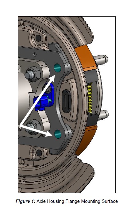
4. Thoroughly clean the inboard mounting surface of the axle housing flange to ensure proper fitment of the new slider pins and base bracket. See Figure 1 for reference.
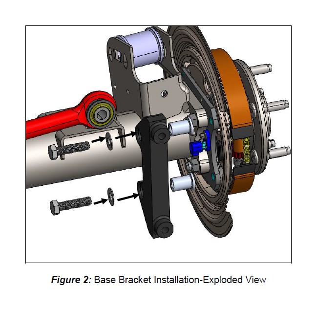
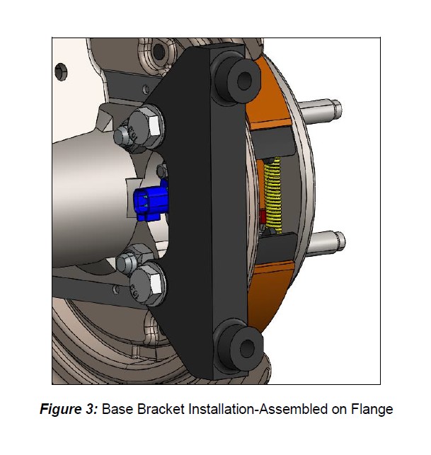
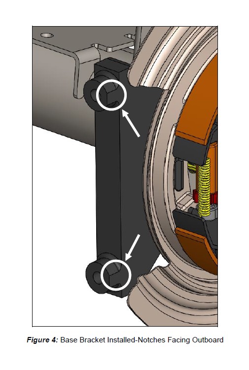
5. Install the new base bracket to the inboard side of the axle housing flange. The side of the bracket with the notches on the caliper mounts, shall face outboard. Secure the bracket using the supplied M12-1.50x50mm hex bolts and 7/16” washers. Hand tighten the bracket for now as shimming will need to be performed in a later step. See Figure 2, Figure 3, and Figure 4 for reference.
6. Install the correct side rotor onto the axle and secure with three lug nuts and washers to prevent scratching the rotor hat.
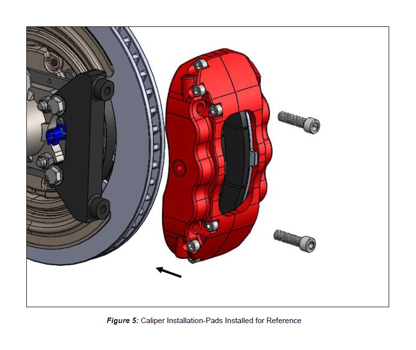
7. With the pads removed, install the new caliper (bleed screw pointing upward) using the supplied M12-1.75 x 45mm socket head bolts. Snug the bolts for now as shimming will require removal. See Figure 5 for reference (pads are shown in the figure for assembly purposes).
8. Perform the shimming procedure, located on the last page. When the procedure has been completed, proceed to Step 9.
9. Install the brake hose to the back of the caliper using the supplied banjo bolt and copper washers (one copper washer on each side of the banjo fitting). Finger tighten the banjo bolt. Connect the hose to the hardline using one of the supplied fittings and install the hose lock. ***IMPORTANT: Position the hose to avoid interference with the wheel and suspension components through the entire range of motion. Tighten fitting and banjo bolt to 15-20 ft-lbs.
10. Repeat the procedure for the other side.
Refer to Bleeding and Pad Bedding & Rotor Seasoning Procedures contained on a separate sheet, or on www.baer.com
For service components and replacement parts contact your Baer Brake Systems Tech Representative.
Shimming Procedure
This style Jeep has a rear axle that allows it to move inboard and outboard. The design of the slider pins on the Baer caliper bracket allow the caliper to follow this movement. However, this must be adjusted to prevent the caliper body from contacting the rotor surface.
Procedure:
1. Push the axle inboard until it stops (this may not move much) and slide the caliper and bracket outboard, against the stop.
2. Using a feeler gauge, measure between the inboard side of the rotor and the caliper body. The minimum clearance must be at least .020”. If this measurement is less, shims will be needed to bring this up to at least .020”.
Before installing shims, check the clearance on the outboard side of the rotor. Pull the rotor outboard until it stops and slide the caliper inboard, against the stop. Measure the gap between the outboard side of the rotor and the caliper body. The minimum clearance must be at least .020”.
If the difference in inboard to outboard measurements is very different (ie. .050” outboard with 0.010” inboard), shims can be used to equalize this. Using that example, a .020” shim between the slider pin and the flange, this would increase the inboard measurement to .030” and decrease the outboard measurement to .030”. Again, the main goal in not less than .020” clearance between caliper body and rotor on both sides.
3. Remove the Socket Head bolts from the caliper and remove the caliper. Loosen the M12- 1.50x50mm bolts securing the base bracket to the flange.
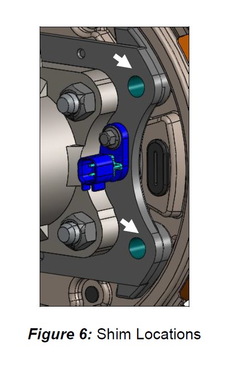
4. Install the appropriate shims (between the slider pin head and axle flange housing), removing one bolt at a time, and snug the same bolts for fit check. See Figure 6 for reference. Install the caliper again for clearance check.
5. Re-shim if necessary. When proper shimming has been achieved, torque the base bracket bolts (M12-1.50x50mm hex bolts) to 97 ft-lbs. Torque the socket head caliper bolts to 75 ft-lbs.