 FREE 1 to 3-Day Delivery on Orders $149+ Details

How to Install Axial LED Halo Headlights w/ Angel Eye DRL & Turn Signals (97-18 Jeep Wrangler TJ & JK) on your Jeep Wrangler
Installation Time
60 minutes
Tools Required
- 1⁄4” Drive Ratchet w/ Extension
- T15 Torx Bit
- Small Razor Knife
- Needle-nose Pliers
- Diagonal Cutters
- Wire Stripper
- Zip Ties
- Soldering Iron (optional)
- Flux core solder (optional)
Installation Instructions:
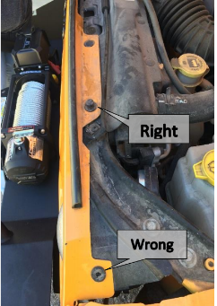
1. Inspect contents. You should have the items shown on the photo to the left. Note: Instructions are not included and there are significant errors on the manufacturer’s
instructions show on the website (highlighted below).

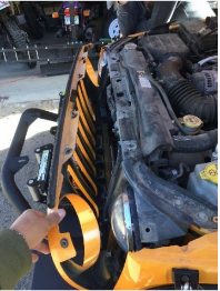
2. Remove grill.
- Open the hood and remove the six plastic fasteners retaining the top of the grill. You can use a small screwdriver to lift the center pin (do not pull it fully out of the fastener). Once the center pins are pulled up, you can remove the fasteners from the grill.
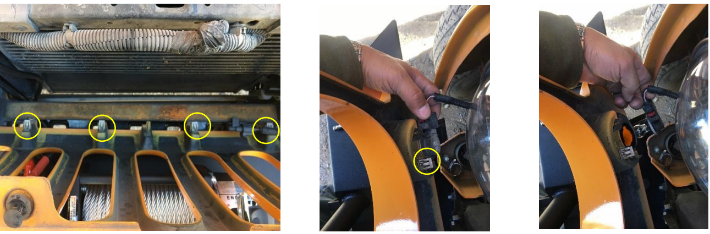
- Next, carefully tilt the grill forward. It will be retained by 6 metal spring clips. Two are near the turn signals and the rest are along the bottom edge. Pull carefully forward (away from the radiator) until they pop loose.
- Finally, remove the turn signal bulbs from the housings in the grill by rotating them to unlock.
- Set the grill and fasteners aside.
3. Remove stock Headlights.
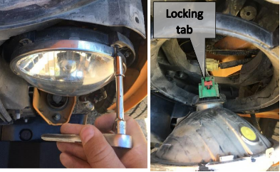
- Use T15 Torx bit to remove the 4 retaining screws on each headlight bezel ring. Remove the bezel ring.
- Remove the headlight by sliding the red locking tab and unplugging the harness from the back of the bulb.
4. Install new headlights.
- Plug headlight jumper harnesses into factory headlight plugs and connect the other end to the new LED bulbs. This will give you basic headlight functionality (high beam and low beam).
- Do not reinstall headlights bezels yet unless halo functionality is not desired.
5. Wire daytime running light (DRL) halos.
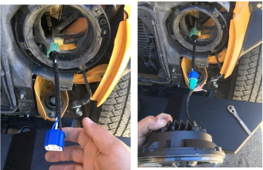
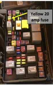
- Open fuse box (located just in front of the battery) and identify the switched power circuit that will provide power for DRL halos. The photo in the manufacturer’s instructions is poor quality and does not clearly identify the appropriate circuit. I chose M6 (20 amp, power outlet #1 and rain sensor). There are probably other options but this one will work.
- Lay the halo power harness out with the circuit tap at the fuse box and each of the connections above a headlight.
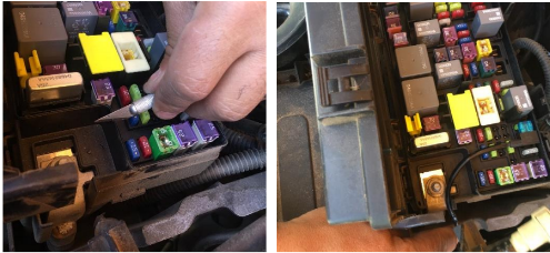
- Remove the fuse in slot M6 and replace it with the circuit tap on the end of the harness.
- Notch the fuse box to pass the wiring harness out after it is closed.
- Route harness out of fuse box and secure with zip ties as needed.
- Route the harness power leads through the back of the headlight housing and connect them to the red leads on the headlight jumper harnesses. A little dielectric grease is a good idea and will make sliding the insulating boots over each other a bit easier.
- This provides DRL functionality to your headlights. If halo turn signal functionality is not required, begin reassembly.
6. Wire halo turn signals.
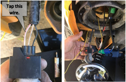
- The manufacturer’s instruction wiring diagram does not match the wiring on the current headlights. The halo turn signal wire is yellow and is spliced into the Jeep’s front turn signals using the included yellow wires.
- The turn signal wire that must be tapped is white with a pink (possibly red) runner. It is located on the back of the turn signal bulb assembly removed at the end of step 2. There are 3 wires here, one black and two white with a runner. The turn signal power
- comes through the outside wire (opposite the black wire) NOT the middle wire.
- Connect the yellow turn signal wire to the headlight jumper harness and route the wire,
- through the back of the headlight bucket, to the turn signal bulb assembly.
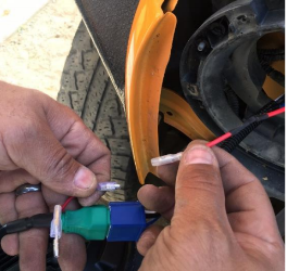
- Trim the yellow wire to length and strip approximately 3⁄4” of insulation from the end.
- There are several methods to tap power from the middle of a wire. In this install I stripped the insulation back and soldered the new connection. To use this method, use a wire strippers to open a gap in the insulation. Wrap the stripped end of the yellow power wire tightly around the exposed turn signal wire, solder, and insulate.
- Repeat for other side.
7. Test for function.
- Halos should illuminate (white only) with the ignition on.
- Halos on the appropriate side should flash orange with turn signals and return to white when signals are turned off.
- High and low beams should function as with stock headlights.
8. Reinstall headlight bezels.
- This process is the reverse of disassembly but ensure wires are neatly tucked behind the headlight.
- The indexing bosses (raised rectangles around the read edge of the headlight) may not perfectly align with the headlight buckets. If this is the case, apply careful pressure to get the plastic bucket to flex and take the headlight.
9. Reinstall the grill. Again, this is the reverse of disassembly
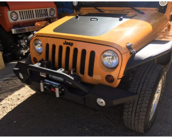
Before
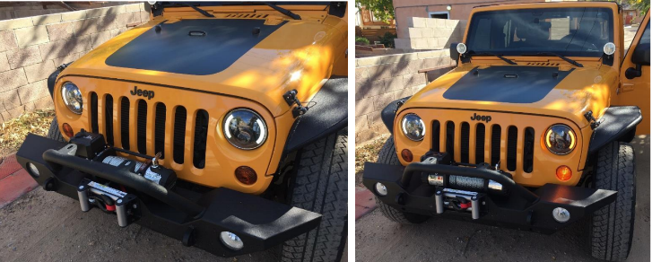
After
Installation instructions written by Clark Adams 12/11/2017

