 FREE 1 to 3-Day Delivery on Orders $149+ Details

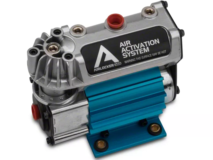
How to Install ARB 12V Compact Air Compressor on your Jeep Wrangler
Installation Time
60 minutes
Tools Required
- 10mm Socket
- Socket Wrench
- Air Compressor Hose
Shop Parts in this Guide
1. Layout all pieces provided to ensure each item arrived (attempting to locate lost items after beginning the installation can cause delays or misfires) (Figure A).
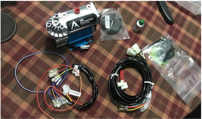
Figure A
2. Locate the pressure switch and the two connectors from the wiring loom provided (Figure B).
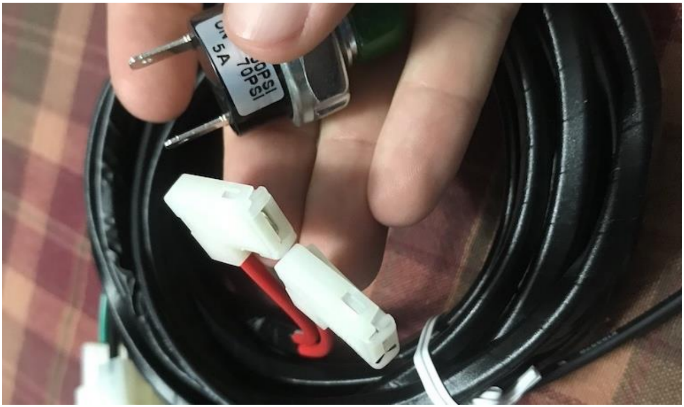
Figure B
3. Connect one of the two connectors by pressing in firmly against the pressure switch (Figure C).
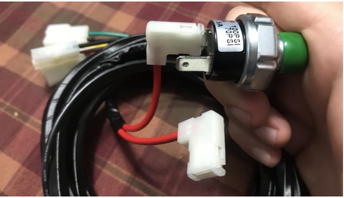
Figure C
4. Repeat Step 3 with the second connector (Figure D).
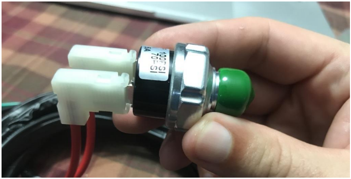
Figure D
5. Thread one of the four supplied bolts into the base of the air compressor, facing away from compressor (Figure E).
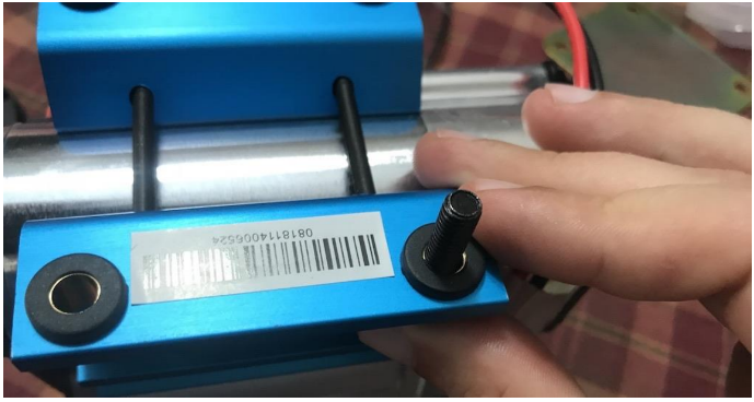
Figure E
6. Insert a second bolt and place the provided base plate over the two bolts to ensure proper alignment (Figure F).
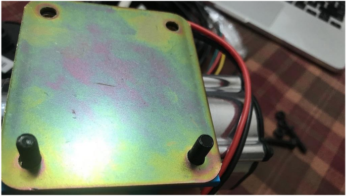
Figure F
7. In order to keep base plate in place, attach the provided nuts; however, these will need to be removed later in order to properly mount the air compressor (Figure G).
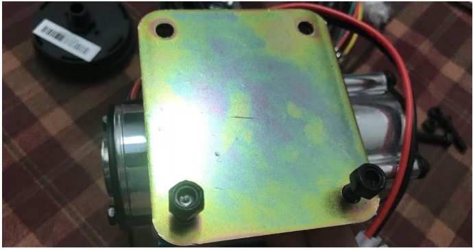
Figure G
8. With the base plate properly connected with all four bolts and nuts, locate the red plug on the side of the air compressor (Figure H).
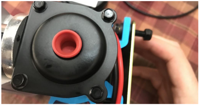
Figure H
9. Remove the plug (Figure I).
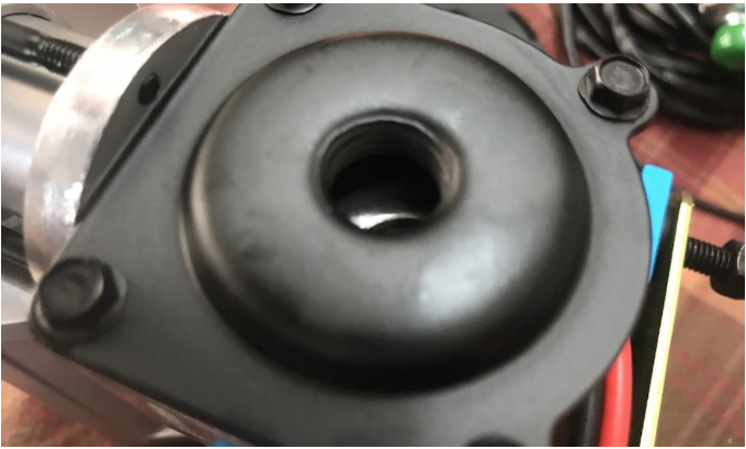
Figure I
10. Locate the filter and screw the filter into the hole where the plug was removed in Step 9 (Figure J).
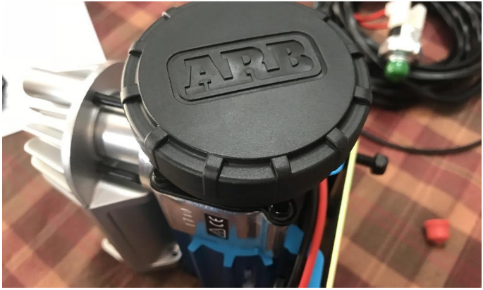
Figure J
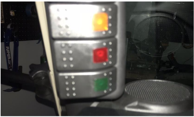
11. Locate the actuator switch and insert the red and yellow wire into the middle connector (Figure K).
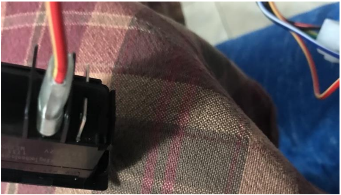
Figure K
12. Insert one of the two black wires onto the connector above the red and yellow wire (Figure L).
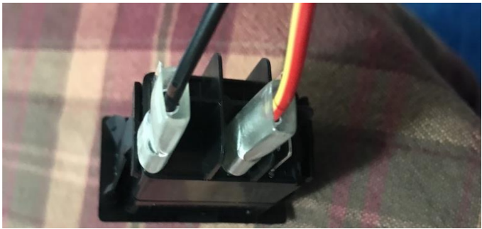
Figure L
13. Insert the other black wire onto the connector to the right of the first black wire connection (Figure M).
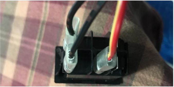
Figure M
14. Connect the red wire below the red and yellow wire (Figure N).
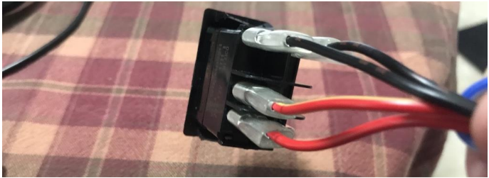
Figure N
15. Connect the blue wire to the right of the red wire connection (Figure O).
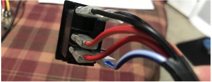
Figure O
16. Locate the other wire loom and the supplied white connector. Clip the red wire into the bottom left connection point of the white connector (Figure P).
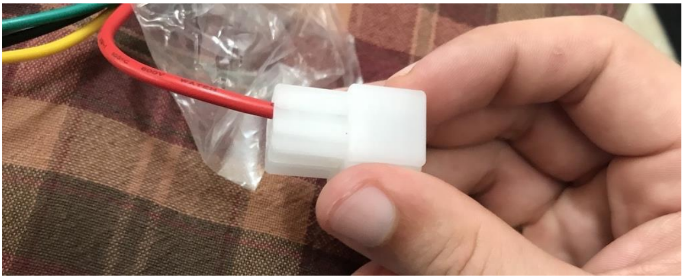
Figure P
17. Connect the yellow wire above the red wire (Figure Q).
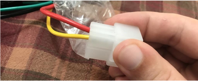
Figure Q
18. Connect the green wire to the right of the yellow wire (Figure R).
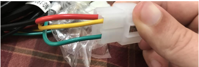
Figure R
19. Connect the black wire below the green wire (Figure S).
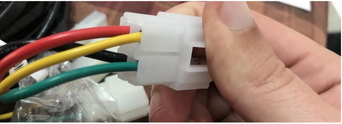
Figure S
20. Mount the air compressor in the desired location (Figure T).
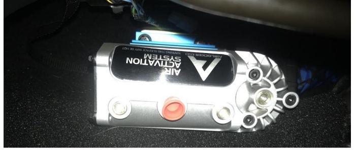
Figure T
21. Attach the ground wire to the chassis and the red and yellow 12v wire to a 12v source. Run the power wiring loom from the air compressor to near the desired switch mounting location (Figure U).
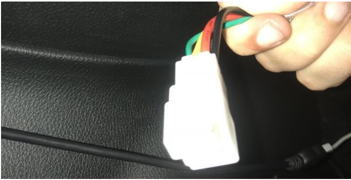
Figure U
22. Connect to the switch wiring loom (Figure V).
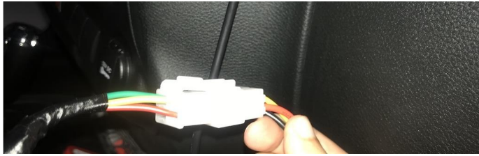
Figure V
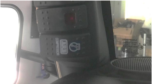
23. Mount the actuator switch and attach the switch cover (Figure W).
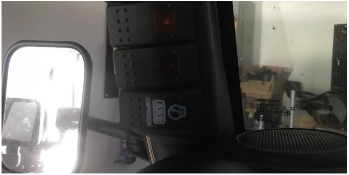
Figure W
24. Attach an air hose (not provided) and flip the dash switch to the air compressor in order to inflate or deflate tires (Figure X).
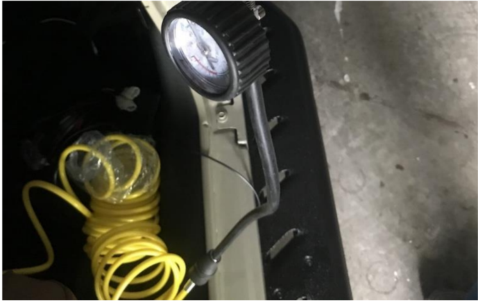
Figure X
Before
After
Installation Instructions Written by ExtremeTerrain Customer J. Sandlin 10/08/2018

