 FREE 1 to 3-Day Delivery on Orders $149+ Details

How to Install an AIRAID Cold Air Dam Intake on your 1991-1995 4.0L Jeep Wrangler YJ
Installation Time
1 hours
Tools Required
- PhillipsScrewdriver
- FlatBladeScrewdriver
- 10mmSocket
- 5/16"
- 7/16"Sockets&Ratchet

Thank you for purchasing the Airaid Intake System. Please read the instruction manual carefully before proceeding with the installation. Contact Airaid @ (800) 498-6951 8:00 AM - 5:00 PM MST weekdays for questions regarding fit or instructions that are not clear to you. Your Airaid Intake System was carefully inspected and packaged. Check that no parts are missing, or were damaged during shipping. If any parts are missing, contact Airaid. The air filter element is protected from direct exposure to water and debris; care should be taken not to drive through deep water. WATER INGESTION IS THE DRIVERS RESPONSIBILTY! The air filter is reusable and should be cleaned using the Airaid Filter Tune-Up Kit periodically.
Thank you for selecting Airaid.
Packing List:
| 700-452 | Airaid Premium Filter | 1 |
| KIT144MAFC | MAF Panel Black | 1 |
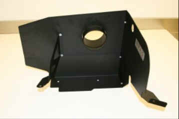
| KIT144BPC | Bottom Panel Black | 1 |
| KIT144BC | Brace | 1 |
| KIT144T | Plastic Intake Tube | 1 |
| KITWSTRIP02 | Weather Strip 32” | 1 |
| KITHUMPHOSE03 | Hump Hose | 1 |
| KIT COUPLER08 | Coupler | 1 |
| KITHOSE01 | ½”x10” Hose | 1 |
| KIT144HP | Hardware & Instructions | 1 |
| KIT09FWZ019 | ¼”” Flat Washer | 4 |
| KIT6NWSAPZ | #6 Flat Washer | 5 |
| KIT6CNKEPZ | 6-32 Keps Nut | 5 |
| KIT6C31MXPPZ | 6-32 x 5/16” Screw | 5 |
| KIT25C62HCSS | ¼-20 x 5/8” Hex Bolt | 3 |
| KIT25CNNES | ¼-20 Lock Nut | 3 |
| KITGRMT05 | Grommet | 1 |
| KITHS48 | #48 Hose Clamp | 2 |
| KITHS60 | #60 Hose Clamp | 2 |
| KITSNP16M4 | Black Speed Clamp | 3 |
| KITSNP14M4 | Black Speed Clamp | 2 |
| KIT09FEZ025125 | ¼” Fender Washer | 2 |
| KITFITTING09 | ¼”NPTx1/2”Barbed Fitting | 1 |
| KITHOSE06 | 3/8”x4” Hose | 1 |
Packing List:
| 700-452 | Airaid Premium Filter | 1 |
| KIT144MAFC | MAF Panel Black | 1 |
| KIT144BPC | Bottom Panel Black | 1 |
| KIT144BC | Brace | 1 |
| KIT144T | Plastic Intake Tube | 1 |
| KITWSTRIP02 | Weather Strip 32” | 1 |
| KITHUMPHOSE03 | Hump Hose | 1 |
| KIT COUPLER08 | Coupler | 1 |
| KITHOSE01 | ½”x10” Hose | 1 |
| KIT144HP | Hardware & Instructions | 1 |
| KIT09FWZ019 | ¼”” Flat Washer | 4 |
| KIT6NWSAPZ | #6 Flat Washer | 5 |
| KIT6CNKEPZ | 6-32 Keps Nut | 5 |
| KIT6C31MXPPZ | 6-32 x 5/16” Screw | 5 |
| KIT25C62HCSS | ¼-20 x 5/8” Hex Bolt | 3 |
| KIT25CNNES | ¼-20 Lock Nut | 3 |
| KITGRMT05 | Grommet | 1 |
| KITHS48 | #48 Hose Clamp | 2 |
| KITHS60 | #60 Hose Clamp | 2 |
| KITSNP16M4 | Black Speed Clamp | 3 |
| KITSNP14M4 | Black Speed Clamp | 2 |
| KIT09FEZ025125 | ¼” Fender Washer | 2 |
| KITFITTING09 | ¼”NPTx1/2”Barbed Fitting | 1 |
| KITHOSE06 | 3/8”x4” Hose | 1 |
1. Disconnect negative battery cable. Remove factory valve cover breather hose from airbox, and valve cover.
1. Disconnect negative battery cable. Remove factory valve cover breather hose from airbox, and valve cover.
2. Unhook vacuum line from airbox, and remove from vehicle at the canister below the master cylinder. (Save for later use.)
2. Unhook vacuum line from airbox, and remove from vehicle at the canister below the master cylinder. (Save for later use.)
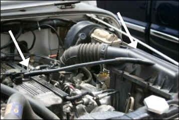
3. Pry open the plastic clamp that holds the factory intake tube to the throttle body. Unhook the 3 metal latches on the airbox that hold it to the mounting plate, and remove the intake assembly.
3. Pry open the plastic clamp that holds the factory intake tube to the throttle body. Unhook the 3 metal latches on the airbox that hold it to the mounting plate, and remove the intake assembly.
4. Remove the two grommets from the airbox mounting plate.
4. Remove the two grommets from the airbox mounting plate.
5. Using a 10mm socket, remove the horn bolt. (Save for later use.)
5. Using a 10mm socket, remove the horn bolt. (Save for later use.)
6. Carefully remove wire loom clamp from hole in fender.
6. Carefully remove wire loom clamp from hole in fender.
7. Assemble the Cool Air Dam as shown using the 5 screws, washers, and nuts provided.
7. Assemble the Cool Air Dam as shown using the 5 screws, washers, and nuts provided.
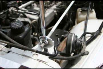
8. Using a 9/16” wrench, loosen the nut on the radiator rod support, and lift it up.
8. Using a 9/16” wrench, loosen the nut on the radiator rod support, and lift it up.
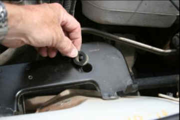
9. Carefully slide the CAD over the support rod, and then slide the supplied grommet over the rod, and into the hole in the CAD as shown. Rotate the CAD and place into position on the factory airbox mount. Reinstall the radiator support rod, and tighten the nut.
9. Carefully slide the CAD over the support rod, and then slide the supplied grommet over the rod, and into the hole in the CAD as shown. Rotate the CAD and place into position on the factory airbox mount. Reinstall the radiator support rod, and tighten the nut.
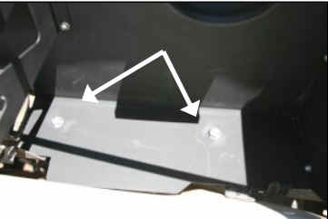
10. Install two ¼”-20 bolts and washers thru the top, and fender washers and nuts on the bottom, where the factory grommets were removed.
10. Install two ¼”-20 bolts and washers thru the top, and fender washers and nuts on the bottom, where the factory grommets were removed.
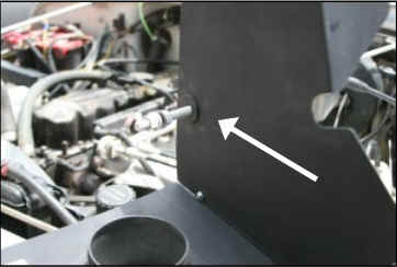
11. Slide the CAD bracket under the horn mount and reinstall the factory bolt from step 5.
11. Slide the CAD bracket under the horn mount and reinstall the factory bolt from step 5.
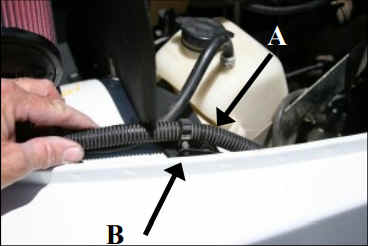
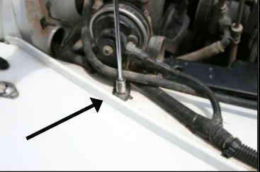
12. A) Using a ¼”-20 bolt, washers, and nut, bolt the CAD to the fender. B) Install the wire loom clamp into the hole in the CAD, as shown.
12. A) Using a ¼”-20 bolt, washers, and nut, bolt the CAD to the fender. B) Install the wire loom clamp into the hole in the CAD, as shown.
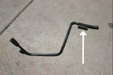
13. Remove the factory hose from step 2, and install the new 3/8”x 4” hose on the end of the vacuum line as shown. Reinstall vacuum line. (Refer to step 2.)
13. Remove the factory hose from step 2, and install the new 3/8”x 4” hose on the end of the vacuum line as shown. Reinstall vacuum line. (Refer to step 2.)
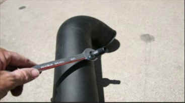
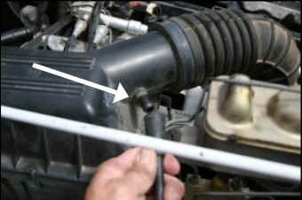
14. Install the ¼” barbed fitting into the intake tube
14. Install the ¼” barbed fitting into the intake tube
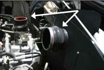
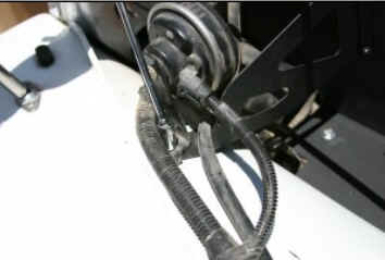
15. Install hump hose on CAD with #52 hose clamps, and the coupler on the throttle body with #44 hose clamps as shown.
15. Install hump hose on CAD with #52 hose clamps, and the coupler on the throttle body with #44 hose clamps as shown.
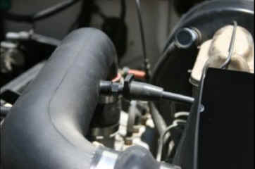
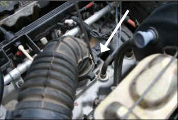
16. Slide intake tube into the hump hose first, and then into the coupler. Adjust for a good fit, and tighten hose clamps. Slide vacuum hose on barbed fitting, and install speed clamp as shown.
16. Slide intake tube into the hump hose first, and then into the coupler. Adjust for a good fit, and tighten hose clamps. Slide vacuum hose on barbed fitting, and install speed clamp as shown.
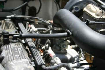
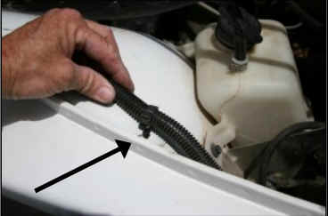
17. Replace the factory breather hose with ½”x10” rubber hose between valve cover and intake tube using speed clamps as shown.
17. Replace the factory breather hose with ½”x10” rubber hose between valve cover and intake tube using speed clamps as shown.
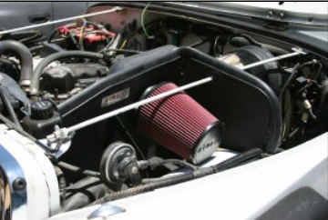
18. Install the Airaid Premium Filter and the weather strip on the CAD, as shown. (Hint: start the weather strip near the radiator support and work towards the back of the vehicle.)
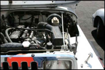
19. Double check your work, make sure all nuts, bolts, and clamps are securely fastened. Make sure there is no foreign material in the intake path. Reconnect the negative battery cable.
18. Install the Airaid Premium Filter and the weather strip on the CAD, as shown. (Hint: start the weather strip near the radiator support and work towards the back of the vehicle.)
19. Double check your work, make sure all nuts, bolts, and clamps are securely fastened. Make sure there is no foreign material in the intake path. Reconnect the negative battery cable.
Before
Before
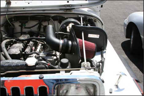
After!
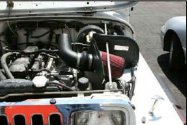
After!
Don’t Forget Your AIRAID Filter Tune-Up Kit!

Don’t Forget Your AIRAID Filter Tune-Up Kit!
P/N 790-550
Included with your Airaid Intake System is a sticker with a California Air Resources Board (C.A.R.B.) Executive Order (EO) number. This sticker must be placed in plain view inside of the engine compartment. Failure to do so may prevent you from passing a smog inspection.
P/N 790-550
Included with your Airaid Intake System is a sticker with a California Air Resources Board (C.A.R.B.) Executive Order (EO) number. This sticker must be placed in plain view inside of the engine compartment. Failure to do so may prevent you from passing a smog inspection.

