FREE 1 to 3-Day Delivery on Orders $149+ Details

How to Install Air Lift Performance 1000 Air Spring Kit (97-06 Wrangler TJ) on your Jeep Wrangler
Installing the Air Lift 1000 System
GETTING STARTED
1. Jack up rear of vehicle or raise on hoist. Support frame with safety stands. Remove lower shock absorber attaching bolts.
2. Mark the upper spring seat and coil spring with a marker so as to index the spring back in the same position upon installation.
3. Lower the axle or raise the body of the vehicle until the suspension has extended far enough to remove the coil spring.
CAUTION: IT MAY BE NECESSARY TO UNBOLT THE BRAKE LINE HANGERS SO AS NOT TO PULL ON THE HOSE DURING THIS STEP. IT MAY ALSO BE NECESSARY TO UNBOLT THE SWAY BAR TO GAIN ADDITIONAL CLEARANCE TO DROP THE AXLE FAR ENOUGH FOR THE LOWER SPRING SEAT ACCESS. NOTE: MOST SWAY BARS UNBOLT FROM THE AXLE, SOME MAY BE ATTACHED TO THE LOWER CONTROL ARM.
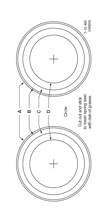
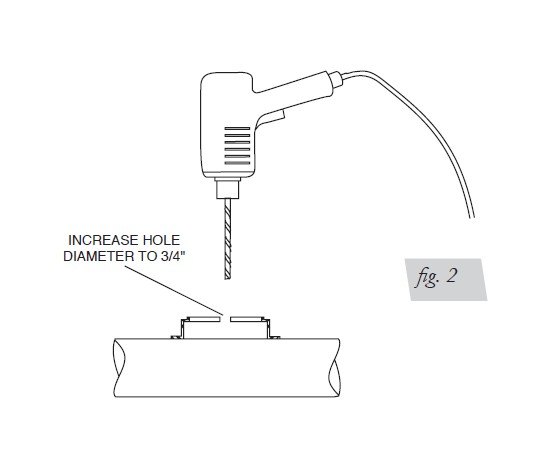
4. A 3/4” access hole must be made for the valve stem. Using the template on the last page, cut out the circle which best fits your model to center punch the lower spring seat for the hose/stem access. Drill a 3/4” hole, or enlarge the existing hole, in the center of the lower spring seat. Option: you can drill the hole out to 1/2” and grind larger as previously suggested. Remove all burrs and sharp edges (Fig. 2).
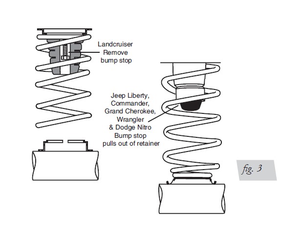
5. LANDCRUISER: using a socket and extension, remove the rubber bump stop from the upper spring seat and discard (Fig. 3).
NOTE: Jeep Liberty, Commander, Grand Cherokee, Wrangler and Dodge Nitro: pull jounce bumper out of cup (Fig. 3).
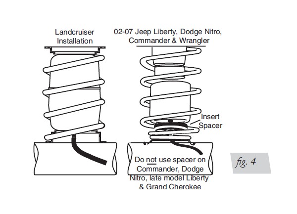
6. Insert air cylinder into coil spring with stem at bottom.
NOTE: 2002-2007 Jeep Liberty & Wrangler: Insert spacers at the bottom between the cylinder and the bottom spring seat (Fig. 4). Do not use spacer for Commander, late model Liberty, Dodge Nitro or the Grand Cherokee.
7. Raise the axle or lower the body to install the coil spring into the spring seats and rotate to proper location marked in step two. Attach the lower shock absorber attaching bolts.
8. Install air line as detailed on pages 5 and 7. A tee air line installation is recommended unless weight in vehicle varies form one side to the other and unequal pressures are needed to level load (or compensate for axle torque transfer in racing application). Dual air lines are used in this case. Proceed with tee air line routing or dual air line routing.
9. Inflate cylinders to 25 lbs. air pressure. Test for air leaks by applying a liquid soap and water solution to all valve cores, fittings and connections.
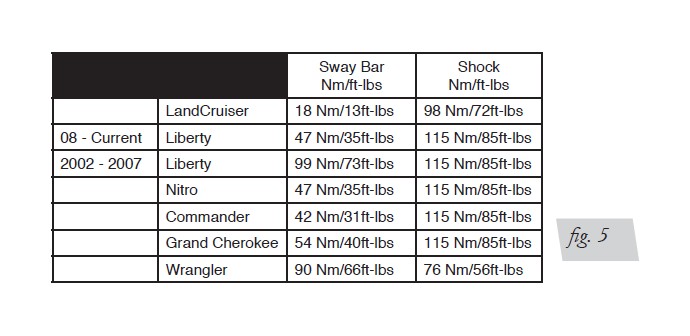
10. Lower the vehicle to the ground. Re-attach all brake lines previously removed and torque all mounting hardware removed per the torque chart supplied (Fig. 5). Recheck air pressure after 24 hours. A 2-4 PSI loss after initial installation is normal. If pressure has dropped more than 5 lbs. re-test for leaks with soapy water solution.
TEE AIR LINE ROUTING
NOTE: Tee air line installation recommended unless weight in vehicle varies from one side to the other and unequal pressures are needed to level the load. Dual air lines are used in this case.
CAUTION: TO PREVENT AIR LINE FROM MELTING, KEEP IT AT LEAST EIGHT INCHES FROM EXHAUST SYSTEM.
A. Locate desired tee location on the frame rail or cross member.
B. Determine and cut adequate length of air line to reach from tee to left and right side on air cylinders.
CAUTION: LEAVE SUFFICIENT AIR LINE SLACK TO PREVENT ANY STRAIN ON FITTING DURING AXLE MOTIONS.
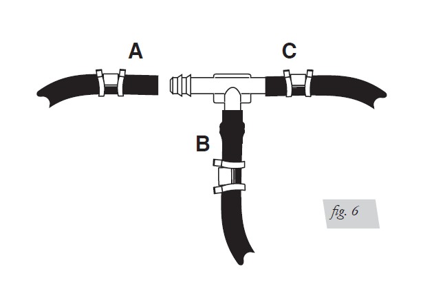
C. Slide air line clamp onto the air line. Push the air line over one side of the tee until all the barbs are covered. Repeat procedure for other leg of tee.
D. With pliers slide the air line clamp forward until it fully covers the barbed section. Repeat for other leg of tee (Fig. 6).
Use this procedure for all air line connections:
A. Slide the air clamp onto the air line.
B. Push the air line over the barbed stem.
C. Compress the ears on the air line clamp with pliers and slide it forward to fully cover
the barbed section.
D. Route along cross member and either lower control arm or upper spring seat to air
cylinder.
E. Insert air line through lower spring seat then slide on air line clamp.
F. Push the air line onto the stem, covering all the barbs. With pliers slide the air line
clamp upward until it fully covers the barbed section (Fig. 7).
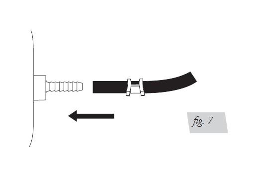
G. Push the remaining air line over the last fitting on tee and route along frame to desired inflation valve location (Fig. 7). Attach with plastic straps or wire.
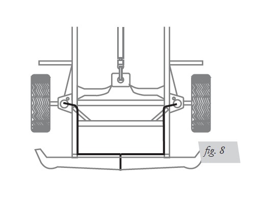
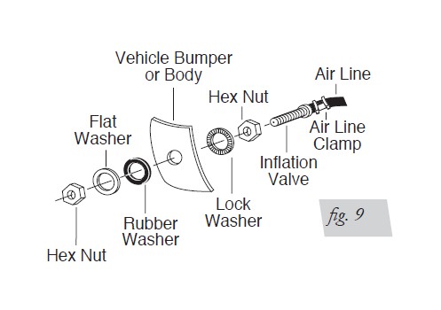
H. Select a location for inflation valve in the gas cap well, the trunk, rear bumper, fender flange or behind the license plate, assuring that the valve will be protected and accessible with an air hose (Fig. 8).
I. Drill a 5/16” hole for inflation valve and mount as in illustration (Fig. 9). Rubber washer is for outside weather seal.
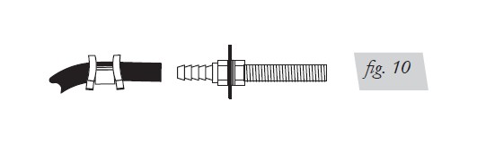
J. Slide air line clamp over the air line. Push air line onto fitting covering all barbs, with pliers slide the air line clamp forward until it fully covers the barbed section (Fig. 10).
K. Raise axle or lower body until air cylinders lightly touch the upper and lower spring
seat.
L. Check TAILPIPE clearance and insure that it is at least 2-3 inches from air cylinder.
If necessary, loosen clamps and rotate or move to obtain additional clearance. If heat
shield is provided, install it.
M. Continue with step 9, page 4.
DUAL AIR LINE ROUTING
CAUTION: TO PREVENT AIR LINE FROM MELTING, KEEP IT AT LEAST EIGHT INCHES FROM EXHAUST SYSTEM.
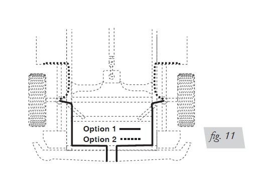
A. Select a location for the inflation valves in the rocker panel flange, or rear bumper,
assuring that each valve will be protected and accessible with an air hose (Fig. 11).
B. Determine and cut adequate length of air line to reach from valve location to left
side air cylinder.
CAUTION: LEAVE SUFFICIENT AIR LINE SLACK TO PREVENT ANY STRAIN ON VALVE STEM DURING NORMAL AXLE MOTIONS.
C. Insert the air line through the lower spring seat.
D. Slide air line clamp onto the cut air line. Push the air line onto the stem, covering
all the barbed section. With pliers slide the air line clamp forward until it fully covers
barbed section (Fig. 10).
E. Repeat process for right side.
F. Drill 5/16” hole for inflating valves and mount as illustrated. Rubber washer is for
outside weather seal (Fig. 9).
G. Route air line along control arm and frame to inflation valve location and cut off
excess air line.
H. Slide air line clamp onto the air line and push the air line over the fitting, covering
all the barbs. With pliers slide the air line clamp forward until it fully covers the barbed
section.
I. Raise axle or lower body until air cylinders lightly touch the upper and lower spring
seat.
J. Check TAILPIPE clearance and insure that it is at least 2-3 inches from air cylinders.
If necessary, loosen clamps and rotate or move to obtain additional clearance. If heat
shields are supplied, install them.
K. Continue with step 9, page 4.
CAUTION: DO NOT INFLATE AIR CYLINDERS BEFORE READING MAINTENANCE/OPERATION TIPS.
CHECKING FOR LEAKS
1. Inflate the air spring to 30 PSI.
2. Spray all connections and the inflation valves with a solution of 1/5 liquid dish soap and 4/5 water. Spot leaks easily by looking for bubbles in the soapy water.
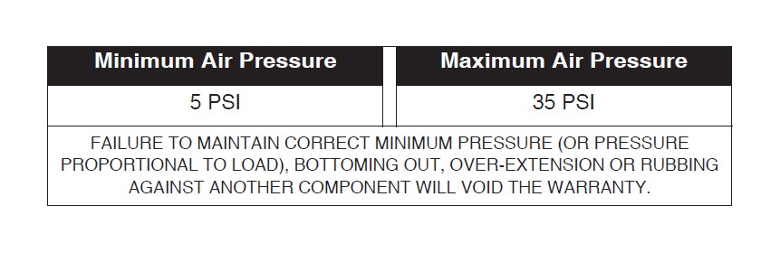
3. After the test, deflate the springs to the minimum pressure required to restore the system to normal ride height. Do not deflate to lower than 5 PSI.
4. Check the air pressure again after 24 hours. A 2 - 4 PSI loss after initial installation is
normal. Retest for leaks if the loss is more than 5 lbs.
FIXING LEAKS
1. If there is a problem with the inflation valve:
a. Check the valve core by tightening it with a valve core tool.
b. Check the air line by removing the air line from the barbed type fitting. Cut the air
line off a few inches in front of the fitting and use a pair of pliers or vice grips to pull/
twist the air line off of the fitting.
CAUTION: DO NOT CUT OFF THE AIR LINE COMPLETELY AS THIS WILL USUALLY NICK THE BARB AND RENDER THE FITTING USELESS.
2. If the preceding steps have not resolved the problem, call Air Lift customer service at (800) 248-0892.
Before Operating
INSTALLATION CHECKLIST (To be completed by installer)
Clearance test — Inflate the air springs to 30 PSI and ensure there is at least 1/2”
clearance around each bellow, away from anything that might rub against them. Be sure
to check the tire, brake drum, frame, shock absorbers and brake cables.
Leak test before road test — Inflate the air springs to 30 PSI, check all connections for leaks with a soapy water solution. See Checking for Leaks on how to spot leaks. All
leaks must be eliminated before the vehicle is road tested.
Heat test — Be sure there is sufficient clearance from any heat sources — at least 6”
for air springs and air lines. If a heat shield was included in the kit, install it. If there is no heat shield, but one is required, call (800) 248-0892.
Fastener test — Recheck all bolts for proper torque. Re-torque after 100 miles.
Road test — The vehicle should be road tested after the preceding tests. Inflate the air springs to 25 PSI (30 PSI if the vehicle is loaded). Drive the vehicle 10 miles and recheck for clearance, loose fasteners and air leaks.
Operating instructions — If professionally installed, the installer should review the Product Use, Maintenance and Servicing section with the owner. Be sure to provide the owner with all of the paperwork which came with the kit.
POST-INSTALLATION CHECKLIST
Overnight leak down test — Recheck air pressure after the vehicle has been used for 24 hours. If the pressure has dropped more than 5 PSI, then there is a leak that must be fixed. Either fix the leak yourself or return to the installer for service.
Air pressure requirements — Regardless of load, the air pressure should always be adjusted to maintain ride height at all times.
Thirty day or 500 mile test —Recheck the air spring system after 30 days or 500 miles, whichever comes first. If any part shows signs of rubbing or abrasion, the source should be identified and moved, if possible. If it is not possible to relocate the cause of the abrasion, the air spring may need to be remounted. If professionally installed, the installer should be consulted. Check all fasteners for tightness.
Product Use, Maintenance and Servicing
MAINTENANCE GUIDELINES
NOTE: By following these steps, vehicle owners will obtain the longest life and best results from their air spring.
1. Check the air pressure weekly.
2. Always maintain normal ride height. Never inflate beyond 35 PSI.
3. If you develop an air leak in the system, use a soapy water solution to check all air line connections and the inflation valve core, before deflating and removing the spring.
4. When increasing load, always adjust the air pressure to maintain normal ride height. Increase or decrease pressure from the system as necessary to attain normal ride height for optimal ride and handling. Remember that loads carried behind the axle (including tongue loads) require more leveling force (pressure) than those carried directly over the axle.
CAUTION: FOR YOUR SAFETY AND TO PREVENT DAMAGE TO YOUR VEHICLE, DO NOT EXCEED MAXIMUM GROSS VEHICLE WEIGHT RATING (GVWR), AS INDICATED BY THE VEHICLE MANUFACTURER. ALTHOUGH YOUR AIR SPRINGS ARE RATED AT A MAXIMUM INFLATION PRESSURE OF 35 PSI, THE AIR PRESSURE ACTUALLY NEEDED IS DEPENDENT ON YOUR LOAD AND GVWR.
5. Always add air to the springs in small quantities, checking the pressure frequently. Cylinders require less air volume than a tire and inflate quickly.
6. Should it become necessary to raise the vehicle by the frame, make sure the system is at a minimum pressure (5 PSI) to reduce tension on the suspension/brake components. Use of on-board leveling systems do not require deflation or disconnection.
OPERATING TIPS
1. Inflate your air springs to 30 PSI before adding the payload. This will allow the air cylinder to properly mesh with the coil spring. After the vehicle is loaded, adjust your air pressure down to level the vehicle and for ride comfort.
2. When carrying a payload it will be helpful to increase the tire inflation pressure in proportion to any overload condition. We recommend a 2 PSI increase above normal for each 100 lbs additional load on the axle.
TROUBLESHOOTING GUIDE
1. Leak test the air line connections.
2. Inspect the air lines to be sure none are pinched. Tie straps may be too tight. Loosen or replace the strap and replace leaking components.
3. Inspect the air line for holes and cracks. Replace as needed.
4. Look for a kink or fold in the air line. Reroute as needed.
If the preceding steps do not solve the problem, it is possibly caused by a failed air spring — either a factory defect or an operating problem. Please call Air Lift at (800) 248-0892 for assistance.
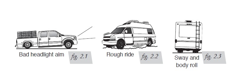
TUNING THE AIR PRESSURE
Pressure determination comes down to three things — level vehicle, ride comfort, and stability.
1. Level vehicle
If the vehicle’s headlights are shining into the trees or the vehicle is leaning to one side,
then it is not level (fig. 2.1). Raise the air pressure to correct either of these problems
and level the vehicle.
2. Ride comfort
If the vehicle has a rough or harsh ride it may be due to either too much pressure or not
enough (fig. 2.2). Try different pressures to determine the best ride comfort.
3. Stability
Stability translates into safety and should be the priority, meaning the driver may need
to sacrifice a perfectly level and comfortable ride. Stability issues include roll control,
bounce, dive during braking and sponginess (fig. 2.3). Tuning out these problems usually
requires an increase in pressure.
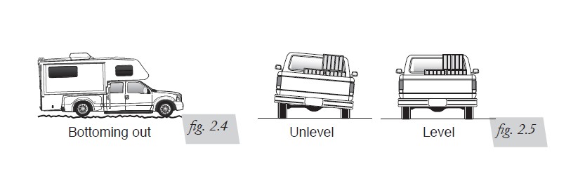
GUIDELINES FOR ADDING AIR
1. Start with the vehicle level or slightly above.
2. When in doubt, always add air.
3. If the front of the vehicle dives while braking, increase the pressure in the front air bags, if equipped.
4. If it is ever suspected that the air bags have bottomed out, increase the pressure (fig. 2.4).
5. Adjust the pressure up and down to find the best ride.
6. If the vehicle rocks and rolls, adjust the air pressure to reduce movement.
7. It may be necessary to maintain different pressures on each side of the vehicle. Loads such as water, fuel, and appliances will cause the vehicle to be heavier on one side (fig. 2.5). As much as a 50 PSI difference is not uncommon.
Choosing the Right On-Board Air Compressor System
Add an on-board air compressor sytem to inflate and deflate your air springs with the touch of a button — from inside or outside of the vehicle.
• For convenient, on-the-go control of your air springs, add an Air Lift on-board air
compressor system.
• Air Lift on-board air compressor systems eliminate the search for gas stations that have a working compressor, saving you time, energy and money.
• All systems include a compressor, controller and all parts needed for easy installation.
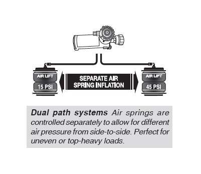
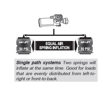
1. Choose single or dual path inflation (see illustrations at right)
2. Choose wireless or analog control
• Wireless: Control your air springs from inside or outside the vehicle. Easiest installation - no wires to the cab.
• Analog: In-cab control of your air springs. Economically priced.
3. Choose heavy or standard duty compressor
• Standard duty: A standard duty compressor will work well for most customers who use their system on an intermittent basis.
• Heavy duty: For daily use, consider the heavy duty compressor - it inflates faster and more quietly than the standard compressor.
Template for use with Air Lift 1000