

How to Install AFE Glide Guard On-Board Air Compressor Mount (07-18 Wrangler JK) on your Jeep Wrangler

Shop Parts in this Guide
• Please read the entire instruction manual before proceeding.
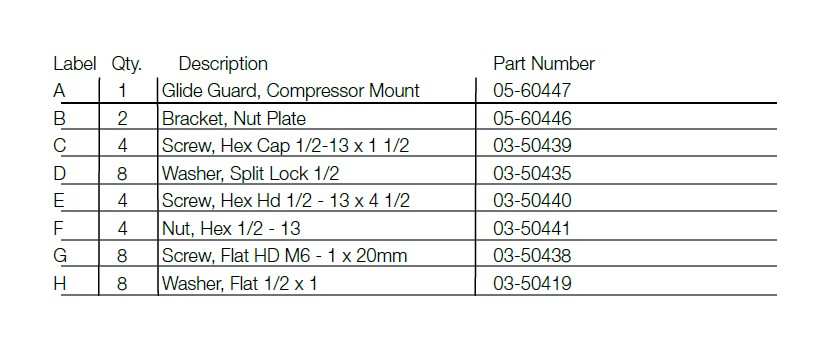
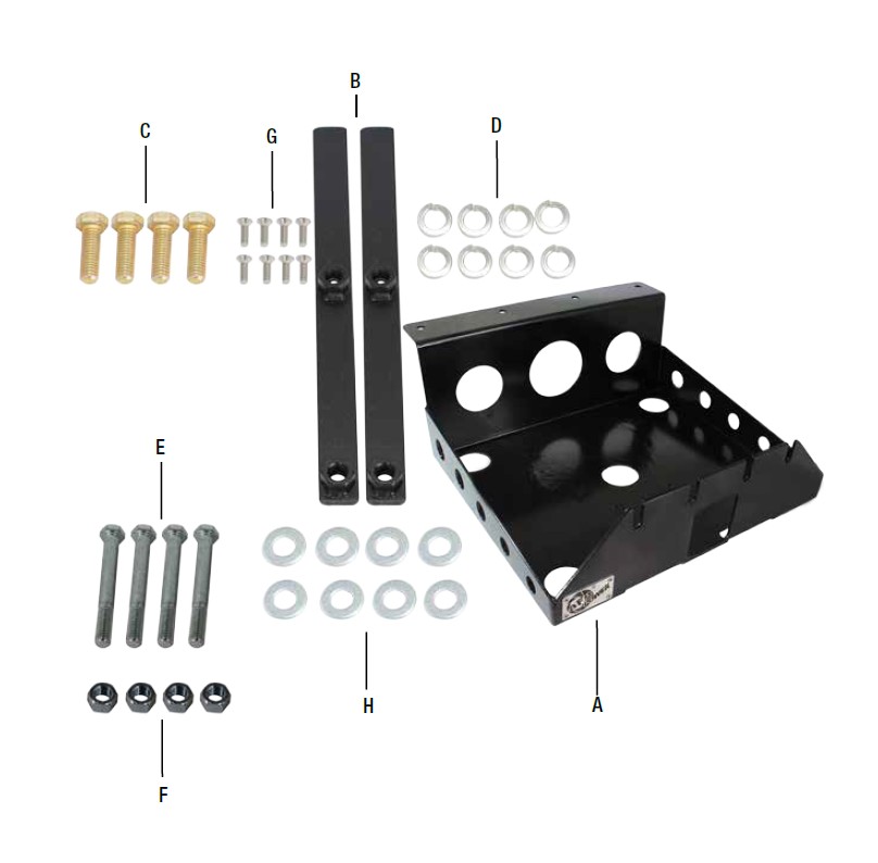
• Ensure all components listed are present.
• If you are missing any of the components, call customer support at 951-493-7100.
• Ensure you have all necessary tools before proceeding.
• Do not attempt to work on your vehicle when the engine is hot.
• Disconnect the negative battery terminal before proceeding.
• Retain factory parts for future use.
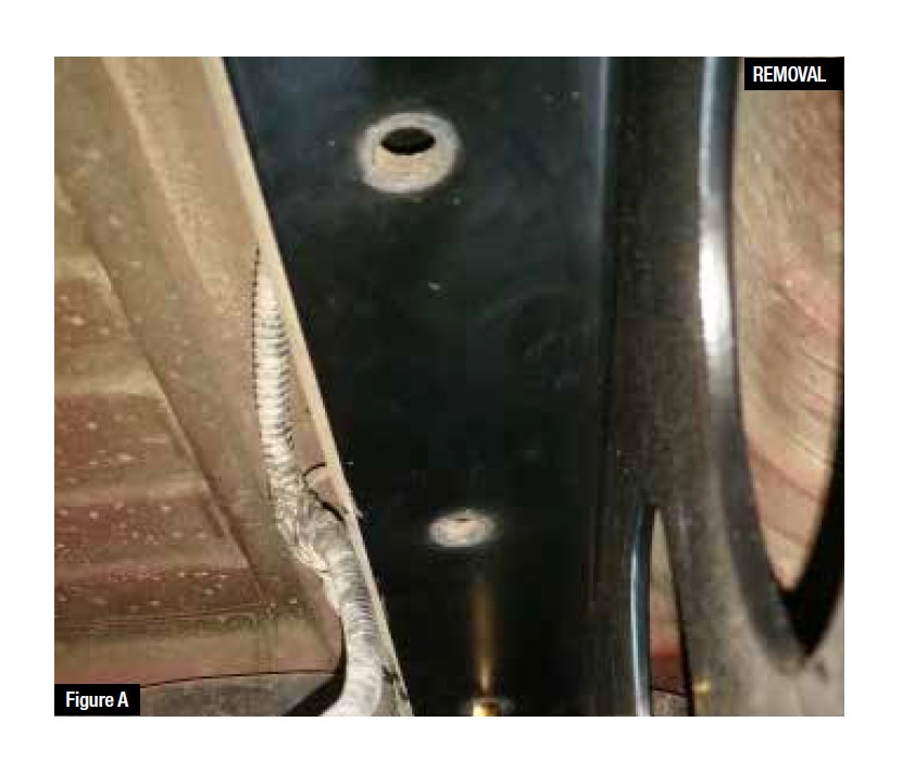
Refer to Figure A for Steps 1-2
1. Loosen but do not remove the 4 factory receiver hitch bolts located on the inside of the rear crossmember.
2. Temporarily install the aFe Glide Guard over the 4 bolts in the receiver hitch and mark the 4 mounting hole locations at the front of the aFe Glide Guard. If not equipped with a hitch, use the (4) 1/2 x 4-1/2 long screws, flat washers, lock washers and nuts.
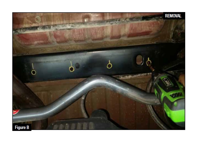
Refer to Figure B for Step 3
3. Remove the aFe Glide Guard. Center punch the 4 holes marked in Step 2 and drill the crossmember using a ½” drill bit.
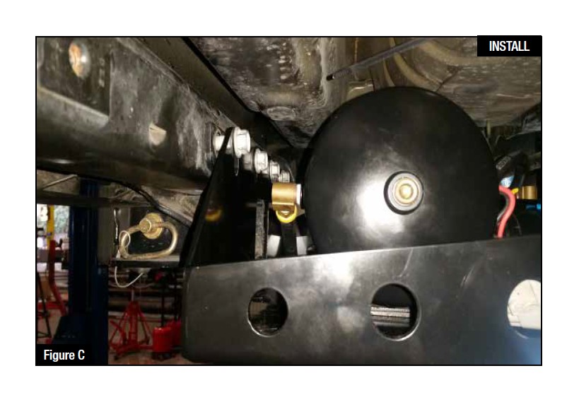
Refer to Figure C for Steps 4-5
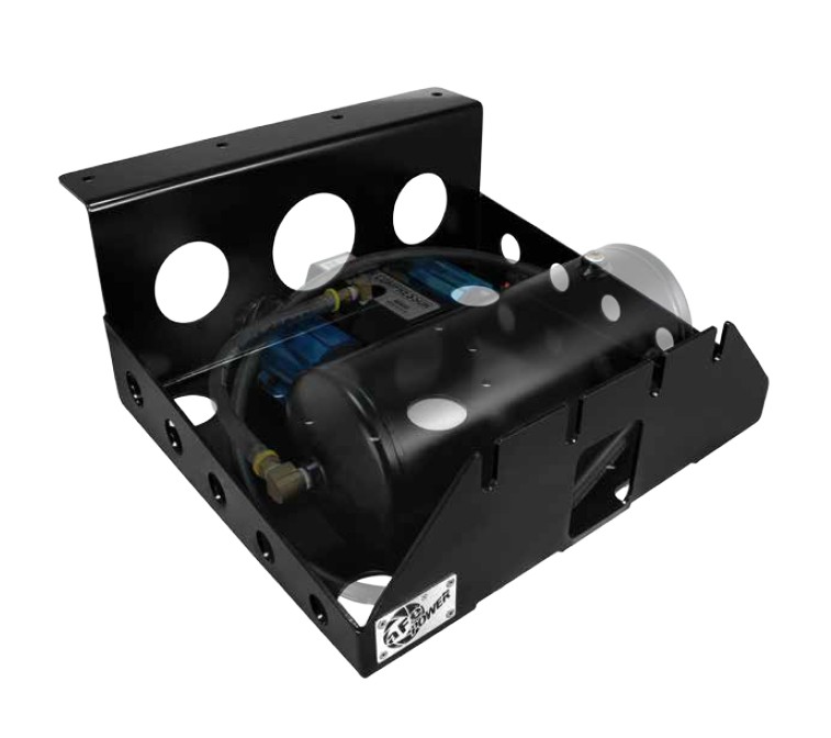
4. Now is the time to install the compressor, tank and related components. A 90mm x 110mm hole pattern is provided for the air tank, with M6 countersunk screws. A 60mm x 225mm hole pattern is provided for the compressor, with M6 countersunk screws,other patterns may be drilled as necessary. Different components may require different hardware. No electrical or air lines are provided in this kit.
5. Install the aFe Glide Guard by sliding it over the 4 receiver hitch bolts or supplied bolts. Using a floor jack, apply pressure to the bottom side of the aFe Glide Guard to hold it in place.
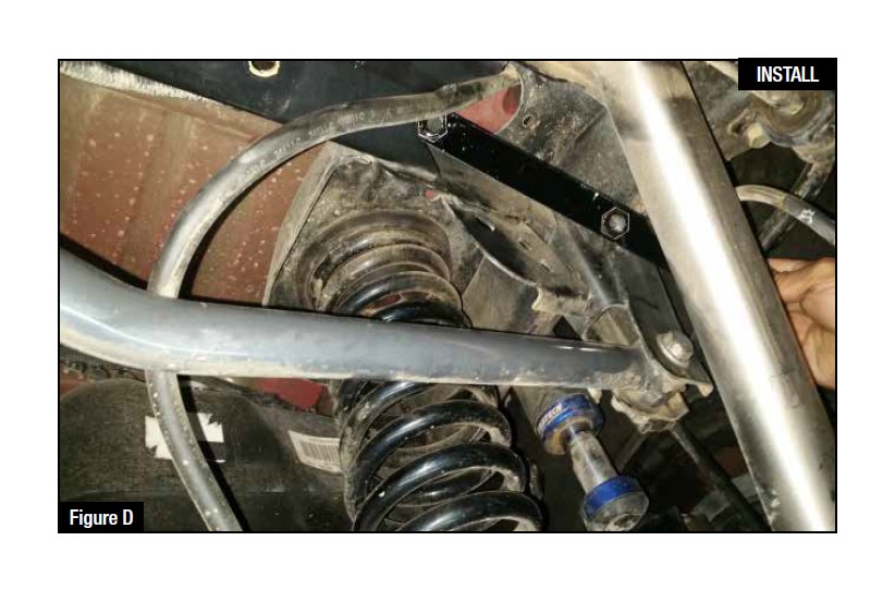
Refer to Figure D for Step 6
6. Locate the 2 nut tabs supplied. Install both nut tabs inside the cross member above
the 4 holes drilled in Step 3.

Refer to Figure E for Steps 7-8
7. Hold the assembly in place with a floor jack and install the (4) short front mounting
1/2 bolts, lock washers, and flat washers.
8. Recheck fasteners for tightness periodically depending on severity of usage. Installation is complete! Enjoy your product.

