 FREE 1 to 3-Day Delivery on Orders $149+ Details

How to Install Zone Offroad J-Flex Adjustable Front Lower Control Arm for 0-6 in. Lift (07-18 Wrangler JK) on your Jeep Wrangler
Tools Required
- JKS1695 or equivalent jam nut wrench
- Hydraulic Floor Jack and Jack Stands
- Metric/Standard Socket Wrench Set
- Torque Wrench
- Anti-Seize Lubricant
- Heavy Duty Ratchet Strap
- Factory Service Manual (recommended)

Shop Parts in this Guide
Welcome
CONGRATULATIONS on purchasing a set of new Control Arms from JKS Manufacturing. We are committed to providing you with the best products available and your satisfaction is our first priority.
PLEASE READ these Installation Instructions carefully, and save them for future reference, as they contain important installation and maintenance information.
Important
SUSPENSION COMPONENTS THAT HAVE RUBBER BUSHINGS must be tightened with vehicle on level ground and at normal ride height. The springs must be supporting weight of vehicle when the hardware is torqued.
RUBBER BUSHINGS MUST NEVER BE LUBRICATED, as doing so will impair performance and longevity.
COMPATIBLE WITH original 4-link suspension configuration and vehicle ride height up to 4.5”.
REFER TO FACTORY SERVICE MANUAL for information and procedures not covered in these instructions.
ATTENTION INSTALLER
Install Control Arms ONE AT A TIME for easiest alignment of mounting hardware.
Installation
1. REMOVE ORIGINAL LOWER SUSPENSION ARM
Raise and support the vehicle chassis with jack stands positioned in rear of the front lower suspension arm brackets.
Raise the front axle housing back into position and support with a hydraulic jack. HINT: The axle housing should be evenly supported and the suspension at normal ride height. Do not attempt removal or installation with the suspension extended, or the axle drooped, as this will place tension on suspension arm mounting hardware.
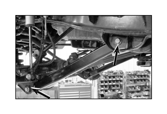
Remove the lower suspension arm bolt and nut from the axle housing bracket. Retain the original mounting hardware.
Remove the bolt and nut from the chassis rail bracket. Retain the original mounting hardware.
Remove the original lower suspension arm from the vehicle.
Proceed to step 2. Complete installation on one side before starting other side.
2. SET CONTROL ARM LENGTH
Determine the ideal arm length for your application by considering factors such as:
Tire Clearance
Steering Clearance
Pinion Angle / Caster
Factory length is 22-5/8"
Max. length is 24 3/8"
Set both control arms to the same length. Lengthening the arms will increase caster and reduce pinion angle.
3. INSTALL CONTROL ARM
Apply anti-seize lubricant to bolt threads of original mounting hardware.
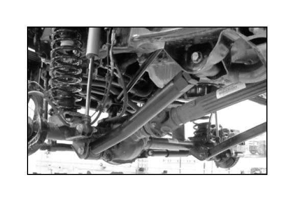
Establish control arm orientation. The arms should be mounted so that the bend goes inward (away from the tire) and the rubber bushing end mounts to the axle.
Mount the control arm to the axle housing bracket. Install the original mounting bolt and finger tighten the nut. DO NOT torque mounting hardware until instructed.
Mount the control arm to the frame rail bracket so the grease fitting is up on the flex eye. Install the original mounting bolt and nut. Finger tighten the bolt.
HINT: If mounting bolt is difficult to install due to misalignment of Control Arm bushing with mounting bracket, either (1) adjust height of axle housing with hydraulic jack, (2) move axle housing into position with a heavy-duty ratchet strap, or (3) temporarily disconnect track bar until mounting holes align.
4. TIGHTEN MOUNTING HARDWARE
Once both control arms have been properly installed, lower the vehicle to the ground until coil springs are supporting the full weight of vehicle.
Using a torque wrench, tighten all mounting hardware to 125 ft-lbs.
Tighten jam nuts using JKS1695 or equivalent.
5. POST-INSTALLATION INSTRUCTIONS
Installing longer lower control arms will affect the vehicle alignment by adding more caster. This may also slightly affect the steering wheel position, making it off-center. It is important that the steering wheel is centered to avoid adverse affects on the vehicle's electronic stability control (ESC) system. JKS recommends having the alignment check by a qualified alignment shop.
Check mounting hardware for proper torque.
Check hardware after 500 miles of use.
Maintenance
Control arm flex ends should be greased regularly as part of vehicle maintenance schedule or after every 4-wheeling trip. Lubricate using marine grade grease. Rubber bushings require no maintenance.
