 FREE 1 to 3-Day Delivery on Orders $149+ Details

How to Install Zone Offroad 4.25 in. Combo Lift Kit w/ Hydro Shocks on your Wrangler

Shop Parts in this Guide
J1425 Installation Instructions 1997-2006 Jeep TJ 4.25” Body/Motor/Suspension Combo Lift
Zone Offroad Products recommends this system be installed by a professional technician. In addition to these instructions, professional knowledge of disassembly/ reassembly procedures and post installation checks must be known. Minimum tool requirements include the following: Assorted metric and standard wrenches, hammer, hydraulic floor jack and a set of jack stands. See the "Special Tools Required" section for additional tools needed to complete this installation properly and safely.
Certain Zone Suspension Products are intended to improve off-road performance. Modifying your vehicle for off-road use may result in the vehicle handling differently than a factory equipped vehicle. Extreme care must be used to prevent loss of control or vehicle rollover. Failure to drive your modified vehicle safely may result in serious injury or death. Zone Offroad Products does not recommend the combined use of suspension lifts, body lifts, or other lifting devices. You should never operate your modified vehicle under the influence of alcohol or drugs. Always drive your modified vehicle at reduced speeds to ensure your ability to control your vehicle under all driving conditions. Always wear your seat belt.
Technical Support
Live Chat provides instant communication with Zone tech support. Anyone can access live chat through a link on www.zoneoffroad.com .
www.zoneoffroad.com may have additional information about this product including the latest instructions, videos, photos, etc.
Send an e-mail to [email protected] detailing your issue for a quick response.
888.998.ZONE Call to speak directly with Zone tech support.
Pre-Installation Notes
1. Special literature required: OE Service Manual for model/year of vehicle. Refer to manual for proper disassembly/reassembly procedures of OE and related components.
2. Adhere to recommendations when replacement fasteners, retainers and keepers are called out in the OE manual.
3. Larger rim and tire combinations may increase leverage on suspension, steering, and related components. When selecting combinations larger than OE, consider the additional stress you could be inducing on the OE and related components.
4. Post suspension system vehicles may experience drive line vibrations. Angles may require tuning, slider on shaft may require replacement, shafts may need to be lengthened or trued, and U-joints may need to be replaced.
5. Secure and properly block vehicle prior to installation of Zone Offroad Products. Always wear safety glasses when using power tools.
6. If installation is to be performed without a hoist, Zone Offroad Products recommends rear alterations first.
7. Due to payload options and initial ride height variances, the amount of lift is a base figure. Final ride height dimensions may vary in accordance to original vehicle attitude. Always measure the attitude prior to beginning installation.
Installation Instructions
It is recommended to install the body lift in conjunction with the motor mount lift, and then install the suspension lift.
Body Lift Installation: Pre-Installation
1. Park the vehicle on a clean flat surface and block the wheels for safety. Place automatic transmissions in park and manual transmissions in neutral.
2. Remove the negative battery cable first, then the positive battery cable. If equipped, the Supplemental Restraint System will be deactivated when the battery is disconnected.
Disassembly
3. Remove the four bolts attaching the front plastic cover to the frame and remove the cover from the frame.
4. If equipped with factory auxiliary headlights on the front bumper, remove the two clips and wiring harness from the fenders.
5. Remove the radiator overflow hose and overflow bottle from the fan shroud and remove it from the vehicle.
6. Remove the four bolts mounting the fan shroud to the radiator and move the shroud back toward the engine, off of the radiator. It will be bolted back on once the motor mount lift is installed Save hardware.
7. Remove the two bolts mounting the steering shaft carrier bearing to the driver’s side frame rail.
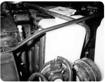
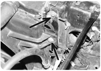
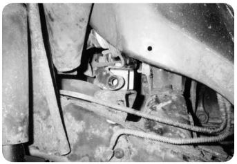
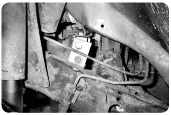
8. Pull back the carpet on the driver’s side near the center console. Remove the four bolts with captive washers. Figure 5 This will free the transfer case linkage bracket from the underside of the body. Save hardware.
9. From underneath, pull down on the linkage bracket and remove it from the linkage. Remove the bracket from the vehicle. Remove the pivot bushing from the bracket. Save all hardware/parts. The relocation bracket will be installed later in the installation.
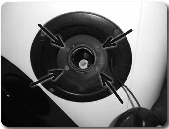
10. Remove the fuel filler cap and remove the four screws mounting the fuel filler neck to the body shroud.
Body Lift
11. Loosen all body mounting bolts (11 in all) but do not remove.
12. Remove the body mounting bolts on the passenger’s side of the vehicle and the front center bolt. Using a hydraulic jack and a wooden block, lift passenger’s side of the vehicle up just high enough for the body spacers to be placed. The front center spacer will not be installed until the entire vehicle has been lifted. Watch for hoses or wires that may be binding or stretching while lifting.
13. Start but do not tighten the new mounting bolts. They are installed in the following locations with the factory bushings/washers: 7/16”-14 x 4” with 3/8” USS washers in the mount over the rear axle and rear mount and 1/2”-13 x 4-1/2” with 7/16” USS washers in the three mounts along the frame under the doors.
14. Repeat installation procedure for the driver’s side of the vehicle and install the front center mount with a 7/16"-14 x 4" bolt and 3/8" USS washer.
15. Check body for correct alignment on the frame. Torque 1/2” hardware to 60 ft-lbs and 7/16” hardware to 40 ft-lbs. Use Loctite on all body mounting hardware.
Assembly
16. Mount the provided steering carrier bearing spacer tube between the steering carrier bearing and the frame. Attach with the 10mm x 60mm bolt through the original mounting hole in the carrier bearing, through the tube, and into the threaded hole in the frame bracket. Do not tighten. Use Loctite on mounting bolts.
17. Install the side strap on the frame with the factory bolt. Do not tighten.
18. Mount the side strap to the carrier bearing using a 7/16” x 1” bolt, nut and SAE washers.
19. Tighten 10mm and 7/16” bolts to 30 ft-lbs.
20. If equipped with factory auxiliary headlights, reconnect and secure the wiring harnesses to the fenders with two zip ties.
21. Reattach the fuel filler neck to the filler shroud with the original screws. It may be necessary to loosen the hose clamps at the filler neck and fuel tank to gain slack in the filler hose to reconnect. Be sure the filler hose is secure on the tank and filler neck and tighten hose clamps. Reinstall gas cap.
Front Core Support Spacers
There are two methods for installing the provided core support spacers. One method requires minor weld while the other is a bolt on application. Each method works equally as well so it will be the installers choice which one to use. Both are methods are outlined below.
No Weld Method
22. Remove the three screws holding the headlight bezels to the core support and remove the bezels from the vehicle. Save bezel and remove hardware.
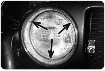
23. Remove headlight.
24. Pull the factory rubber core support bumpers from the bottom of the core support.
25. Locate the provided square core support spacers. Install a provided 3/8" x 1" bolt/washer through one of the holes from the inside out. Lightly grease and install the factory core support bumper into the remaining hole in the spacer. The bolt head will be inside the tube with the threads pointing out.
26. Attach the core support spacer to the original hole and fasten with a 3/8" nut and washer. The end of the bolt is accessed through the headlight hole in the grill. Tighten the 3/8" hardware securely.
27. Reinstall the headlight and bezel.
28. Install the Jeep front cover with the four factory bolts. Tighten securely.
Weld Method
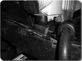
29. Locate the provided core support spacers. These will be positioned between the frame and factory rubber core support bumpers.
30. Position the core support spacers between the frame and factory rubber support. Tack weld the spacer in place. Only enough weld to keep the spacers in place is needed. Allow the area to cool and paint to prevent corrosion.
31. Install the Jeep front cover with the four factory bolts. Tighten securely.
Transfer Case Linkage
1. Mount the pivot bushing to the relocation bracket with the provided 1/4" hardware. Mount the pivot bushing relocation bracket to the factory bracket with the factory hardware. Torque all mounting hardware to 10 ft-lbs
2. Install the modified bracket assembly in the original location under the floorboard by sliding the linkage rod through the pivot bushing. Fasten the bracket to the floorboard using the factory hardware. Torque hardware to 10 ft-lbs.
3. Check the 4wd lever operation to ensure that there is engagement in all ranges. Adjust the linkage as necessary.
Motor Mount Lift Installation
Pre-Installation Notes
1. This kit will be installed on one side of the vehicle at a time.
2. This system uses the factory motor mounts. New mounts must be installed if existing rubber isoloators are worn or mounting studs are in bad condition.
Motor Mount Disassembly
3. Position a floor jack under the transmission bellhousing with a block of wood to distribute the engine weight
4. Carefully raise the jack just enough to remove the weight of the engine from the motor mounts.
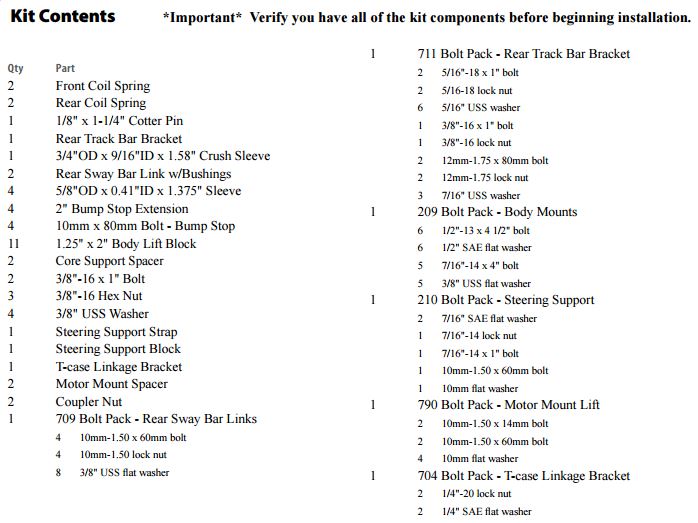
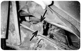
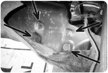
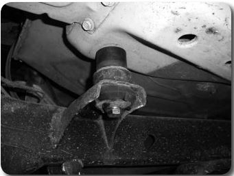
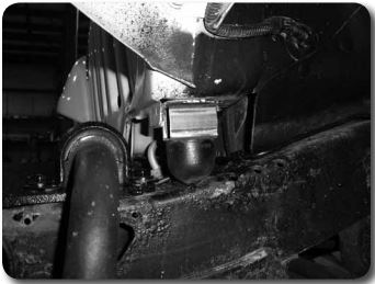
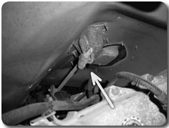
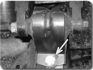
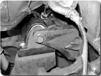
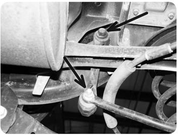
5. There is one fastener on the top side Figure 1a and one on the bottom Figure 1b of the engine mounts. Remove these from the passenger side motor mount using a 15 mm socket.
6. Remove the nut from the cross bolt that mounts the rubber isolotor to the passenger side engine bracket and remove the cross bolt (18mm). Remove the motor mount from the vehicle. Retain hardware.
Step 6 Note:
Vehicles equipped with a 4 cyl motor will need to remove the alternator to remove the cross bolt. Vehicles eqiupped with air conditioning have a condenser pump that will prevent the cross bolt removal. In this case, the engine support bracket will need to be removed from the engine.

Motor Mount Modification - 4 Cyl. Jeep YJ Models
7. The Jeep YJ's equipped with a 4 cylinder engine have a slightly different passenger side motor mount configuration that requires a few extra steps. If you do not have a 4 cyl YJ proceed to step 10.
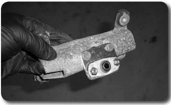
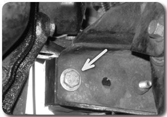
8. There is an additional mounting plate between the motor mount and frame on some 4 cylinder models that needs to be removed. Using a 15mm wrench remove the remaining nut holding the mounting plate to the motor mount.
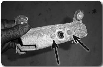
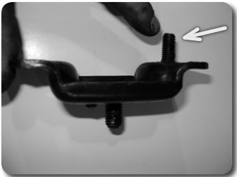
9. The outside stud on the mounting plate where the nut was just removed needs to punched out. Figure 3. This can be removed by setting the plate across the jaws of a vice and hitting the stud through with a hammer. This stud will be replaced with the hardware in the kit.
Step 9 Note:
If a bench vise is not available, use two blocks of wood.
Motor Mount Modification - All Models
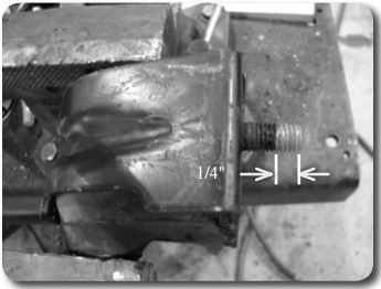
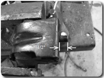
10. Locate the motor mount and using a hacksaw or appropriate cutting tool, cut 1/4" of threads from the end of the engine mount stud to leave a 1/2" of threads remaining. Take care not to damage the threads. Take care not to remove too little or too much of the thread to ensure proper thread engagement with the mating hardware to be installed.
Step 10 Note:
It can be helpful to thread a nut onto the stud before cutting so once removed it will help correct any thread deformation.
11. Apply Loctite on the threads and install the supplied 10mm coupling nut onto the modified motor mount stud and tighten to 30 ft lbs.
12. Locate the provided motor mount spacer and place it under the engine mount aligning the large hole in the spacer with the coupler nut.
Motor Mount Lift Installation - Non-4 Cylinder Models
13. Install the motor mount assembly onto the frame in the same orientation as removed and align bolt hole in the motor mount and spacer to the threaded hole in the frame. Looseley thread the 10mm x 60mm bolt with washer into the frame. From the bottom of the mount thread the 10mm x 14mm bolt with washer into the coupler nut on the motor mount. Use Loctite on all threads. Do not tighten at this time. Skip to step 16.
Motor Mount Lift Installation - 4 Cyl. Jeep YJ Models
14. Locate and sandwich the provided motor mout spacer between the motor mount and mouting plate by threading the 10mm x 15mm bolt and washer into the coupler nut from previous step. Insert the 10mm x 60mm bolt and washer where the stud was removed from the mounting plate so it goes up through the motor mount from the bottom and attach with the factory nut. Use Loctite on all threads. Tighen bolts to 30 ft lbs.
15. Install the motor mount assembly onto the frame in the same orientation as removed and align the lower stud to the hole in the frame. Loosely install the factory nut on the stud to attach the motor mount to the frame.
Motor Mount Lift Installation - All Models
16. Locate the factory cross bolt and nut and re-install the motor mount to the engine bracket. It may be necessary to adjust the height of the jack to align the botlt with the motor mount.
17. If the alternator or engine bracket had to be removed in the previous steps, reinstall them at this time.
18. Proceed to drivers side installation. Motor mount hardware will be tightened once both sides have been installed. On 4 cylinder YJ models follow steps 10- 13 for the driver's side motor mount modification and installation.
19. Once both sides have been installed tighten all 10mm hardware to 30 ft. lbs and the cross bolt to 60 ft lbs.
20. Install radiator fan shroud to the radiator with the four factory bolts. Tighten securely.
21. Install the overflow bottle and overflow hose to the radiator and fan shroud.
Post-Installation Notes
22. Before starting the engine, check clearance between the fan blades and fan shroud. If necessary trim the fan shround until there is no interference.
23. Check torque on all hardware.
24. Reconnect battery cables. Connect positive first, then negative.
25. Retorque hardware after 500 miles.
Suspension Lift Installation
Pre-Installation Notes
1. Park the vehicle on an appropriate work surface. Ensure that the vehicle is in park for automatic transmission or in first gear for manual transmissions and the parking brake is applied. Block the wheels for added safety.
2. If equipped, remove the foward transmission skid plate. Remove the two frame mount bolts (one per side) and three center skid plate bolts. Remove the skid plate from the vehicle.
Step 2 Note:
As a result of the increased suspension travel of this system, the auxilary forward transmission skid plate cannot be reinstalled. Installation of the skid plate will result in contact with the front driveshaft under normal suspension travel, possibly causing damage to the driveshaft.
Step 3 Note:
The track bar bolt typically requires a 15mm socket but may require a T‑50 Torx socket on early models.
Front Installation
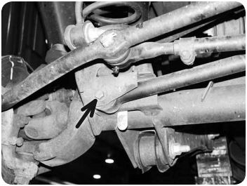
3. Remove the bolt mounting the front track bar to the passenger’s side of the axle. Save track bar bolt and nut tab. Allow the track bar to hang free.
4. Raise the front of vehicle with a hydraulic jack and place jack stands under the frame rails, just behind the lower control arm pockets.
5. Remove the wheels.
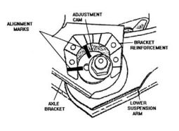
6. 1997 model TJ only: Mark the position of the alignment cam adjusters located at the end of each front lower control arm at the axle.
7. Support the front axle with a hydraulic jack. Remove the shocks using a 13mm socket and wrench at the lower mount and a 15mm wrench at the stud. It may be necessary to keep the stud from spinning using a 1/4" wrench. Save the lower shock hardware.
8. Remove the upper mounting nut (15mm) from the sway bar links. Disconnect the links from the sway bar with a pickle fork to release the tapered seat.
9. Disconnect the sway bar link from the axle. Remove the nut (19mm) and the sway bar link from the bolt. Some early models will require a T55 torx socket to hold the bolt from rotating. Later models used a bolt with a serrated neck that is pressed into the bracket so it will not rotate. Save mount axle hardware.
10. Remove the cotter pin and castellated nut from the drag link end at the pitman arm. Thread the nut back on a couple of turns. Strike the pitman arm near the drag link end to release the tapered seat. Take care not to damage the end. Remove the nut (19mm) and the drag link from the pitman arm. Save hardware.
11. Remove the driver’s side coil spring retainer clip located on the back side of the axle coil seat using a 13mm socket. Save clip and bolt.
12. Ensure that the axle is well supported with a jack. Loosen and remove the driver’s and passenger’s side lower control arm bolts at the axle (21mm). This will allow the axle to lower enough to remove and install the coil springs. Save the control arm hardware.
Step 12 Note:
It may be necessary to disconnect the brake line brackets from the frame to allow the axle to lower enough to remove the springs. This will require a T40 torx socket.
13. Lower the axle with the jack and take care not to over extend the brake lines. Remove the original coil springs.
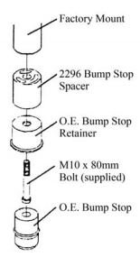
14. Remove the factory bump stop from the upper coil mount. Large pliers can be used to pull it out. Remove the factory bump stop retainer cup by removing the bolt (15mm) from the center.
15. Install the provided 2" bump stop spacer between the factory retainer cup and the frame with a 10mm x 80mm bolt. Torque the bolt to 30 ft-lbs. Reinstall the factory rubber bump stop in the retainer.
Note: A small amount of grease on the bump stop will make installation easier.
16. Install the new coil springs and rotate the ends so that they seat properly in the axle mounts.
17. Raise the axle until the coils seat in the upper mounts. Reinstall the driver’s side coil retainer and torque to 20 ft-lbs.
18. Reattach the driver's and passenger’s side lower control arm bolts/nuts/washers. Snug the bolts but do not tighten completely and ensure the washers are inside the cam stops on the axle. Both lower control arm bolts will be tightened with the weight of the vehicle on the suspension.
19. Install the new shocks with the provided upper bushings/hardware. Leave the upper nut loose.
20. Attach the shock to the axle with the original shock hardware. Torque bolts to 20 ft-lbs. Go back and tighten the upper shock stem nut until the stem bushings begin to swell. Install the thin jam nut on the stem and tighten it against the first nut.
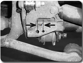
21. Locate the factory track bar mount on the passenger's side of the axle. Measure from the center of the original track bar mounting hole 3/4" toward the driver's side and mark. Drill a 13/32" hole at the mark through the front and back faces of the track bar mount. This will be the new mounting point for the track bar. Do not install the track bar at this time.
22. Reattach the drag link to the pitman arm with the original castellated nut. Torque the nut to 60 ft-lbs. Align the cotter pin hole with the slots in the nut and install the new provided cotter pin. Never loosen the nut to align the cotter pin, only tighten.
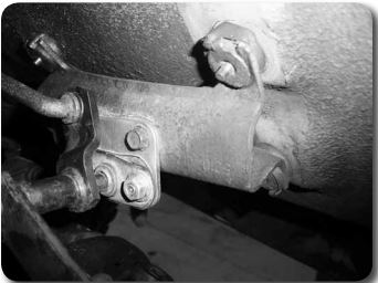
23. Install the provided sway bar link u-brackets to each end of the sway bar using 10mm x 40mm bolts, nuts and 3/8" USS washers. Install the bolt up through the bracket and sway bar hole. Position the bracket so the holes are facing the same direction as the hole on the axle for the sway bar mount Figure 8. Torque bolt to 40 ft-lbs.
24. Locate the new front sway bar links. The front links have offset eyes. Install a 5/8"OD x 0.480" ID steel sleeve in one end and a 5/8"OD x 0.407ID sleeve in the other end of each link. The links will have the bushings preinstalled.
25. Attached the new sway bar links to the axle mount with the factory hardware and to the new sway bar u-bracket with 3/8" x 2-1/2" bolts, nuts and washers run from inside out. The end with the smaller ID sleeve will mount to the u-bracket. When mounted correctly, the links will taper in toward the center of the vehicle as the run from the axle to the sway bar. Torque the factory hardware to 55 ft-lbs and 3/8" hardware to 30 ft-lbs.
Step 23-25 Note:
If the sway bar disconnects were purchased with the kit instead of fixed front links, reference the sway bar disconnects instruction sheet..
26. Install the wheels and torque the lug nuts to the manufacturer’s specs. See vehicle owner’s manual.
27. Remove the jack stands and lower the vehicle to the ground.
28. Bounce the front of the vehicle to settle the suspension.
29. Connect the front track bar to the newly drilled hole in the axle mount with the original hardware. Torque bolt to 50 ft-lbs. Note: To aid in aligning the track bar hole have an assistant turn the steering wheel to shift the trackbar in the correct direction.
30. Torque the lower control arm bolts to 85 ft-lbs.
Note: If working on a 97 model, be sure to align the marks made at the beginning of the installation before tightening the bolts.
31. Check all hardware for proper torque.
Rear Installation
1. Disconnect the rear track bar from the passenger’s side frame mount using a 15mm socket and 18mm wrench. Save hardware.
2. Raise the rear of vehicle with a hydraulic jack and place jack stands under the frame rails, just ahead of the lower control arm pockets.
3. Remove the wheels.
4. Support the rear axle with a hydraulic jack. Remove the shocks using a 13mm socket on the upper mounts and 15mm socket and 18mm wrench on the lower mount. Save all shock hardware.
5. Disconnect the sway bar links from the sway bar and frame using a 15mm socket and 18mm wrench. Save hardware.
6. Lower the axle with the hydraulic jack and remove the coil springs.
7. Remove the factory bump stop from the upper coil mount. Large pliers can be used to pull it out. Remove the factory bump stop retainer cup by removing the bolt (15mm) from the center.
8. Install the provided 2" bump stop spacer between the factory retainer cup and the frame with a 10mm x 80mm bolt. Torque the bolt to 30 ft-lbs. Reinstall the factory rubber bump stop in the retainer.
9. Remove the plastic cover from the track bar mount on the driver's side of the axle. Discard the cover
10. Disconnect the track bar from the axle by removing the Torx head bolt (T55). Note how the track bar in positioned in the vehicle. It can rest in the vehicle or be removed for reinstallation later.
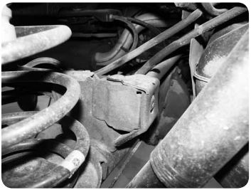
11. Position the supplied track bar relocation bracket on the original track bar axle mount. Install the provided 3/4"OD x 9/16"ID x 1.58" crush sleeve in the original track bar mount point. Install a provided 12mm x 80mm bolt and 7/16" washer through the supplied bracket, factory mount, sleeve and out through the other side of the mount. Loosely fasten with the factory nut tab. If the factory is damaged, use a provided 12mm nut.
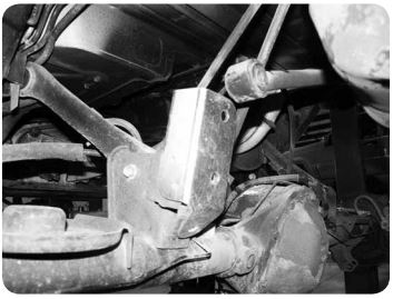
12. With the new bracket in place, drill out the remaining three holes using the bracket as a template. The lowest hole is 3/8" while the top and side is 5/16". Fasten the bracket with the supplied 3/8" x 1" bolt, nut and washers in the lower hole and 5/16" x 1" bolts, nut and washers in the remaining holes. Torque the 3/8" bolt to 30 ft-lbs and the 5/16" to 22 ft-lbs. Go back and torque the 12mm main bolt to 60 ft-lbs.
13. Install the factory track bar in the new bracket with the provided 12mm x 80mm bolt, nut and 7/16" washers. The bolt must be installed from back to front. Leave the bolt loose.
14. Install the new coil springs in the upper and lower spring seats. Note: The coils have identical ends so they mount in either direction.
15. Lightly grease and install the provided hourglass bushing and steel sleeve in the rear shock eyes. Note: One end will have a bar pin preinstalled.
16. Attach the new shocks to the frame with the original hardware. Torque bolts to 20 ft-lbs.
17. Raise the rear axle until the shocks can be fastened to the axle mounts with the original hardware. Torque bolts to 55 ft-lbs.
18. Locate the new rear sway bar links with preinstalled bushings. Install the provided 5/8" OD x 0.407ID steel sleeves in each link end.
19. Install the rear sway bar links to the original frame mounts and the sway bar with new 10mm x 60mm bolts, nuts and washers. Torque bolts to 30 ft-lbs. The factory 10mm nut tabs can be reused at the frame mounts.
20. Install the wheels and torque the lug nuts to the manufacturer’s specs. See vehicle owner’s manual.
21. Remove the jack stands and lower the vehicle to the ground. Note: Make sure the track bar doesn't get pinched when lowering the vehicle.
22. Bounce the rear of the vehicle to settle the suspension.
23. Reattach the rear track bar to the passenger’s side frame mount with the original hardware. Have an assistant push on the side of the body to help align the track bar in the bracket. Torque frame and axle bolts to 70 ft-lbs
Post-Installation
24. A front end alignment is required to adjust toe-in setting as well as straighten the steering wheel. Caster can be adjusted on 97 models using the factory alignment cams bolts. Zone Suspension offers replacement cam bolt kits for all 97-06 models, part #J5311.
25. Check all hardware for proper torque & again after 500 miles. Check hardware at regularly scheduled maintenance intervals.
26. Adjust headlights.
Post-Installation Warnings
Check all fasteners for proper torque. Check to ensure for adequate clearance between all rotating, mobile, fixed, and heated members. Verify clearance between exhaust and brake lines, fuel lines, fuel tank, floor boards and wiring harness. Check steering gear for clearance. Test and inspect brake system.
Perform steering sweep to ensure front brake hoses have adequate slack and do not contact any rotating, mobile or heated members. Inspect rear brake hoses at full extension for adequate slack. Failure to perform hose check/ replacement may result in component failure.
Perform head light check and adjustment.
Re-torque all fasteners after 500 miles. Always inspect fasteners and components during routine servicing.
