 FREE 1 to 3-Day Delivery on Orders $149+ Details

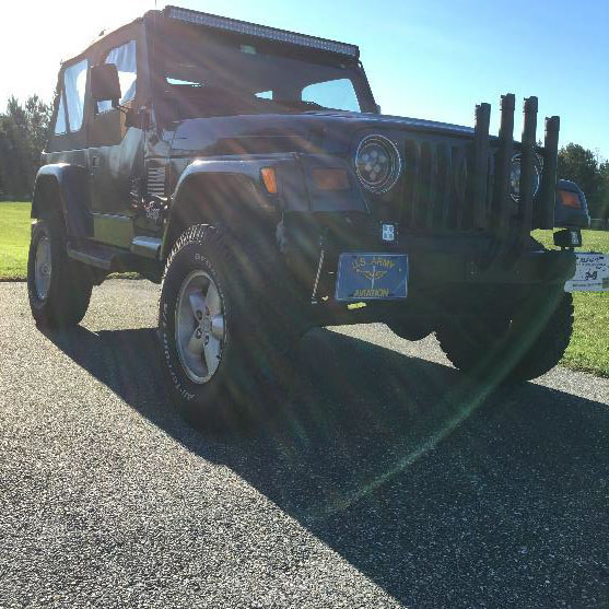
How To Install a Zone Offroad 3 In. Lift Kit w/ Hydro Shocks On Your 1997-2002 Jeep Wrangler TJ
Installation Time
6 hours
Tools Required
- Hydraulic Jack
- Assorted Socket Wrench Set
- Assorted Wrench Set
- Torx T40, T45, T55 Sockets
- Torque Wrench 0-100 ft-lbs
- Vice Grips
- High-Speed Drill
- Assorted Metal Drill Bits
- Hammer
- Center Punch
- Spring Compressor
- Small Pickle Fork
- Large Pliers

Secure and block vehicle prior to installation. Utilize Personal Protective Equipment and personal safety at all times.
If installation is completed without a vehicle lift, begin with rear alterations first.
Consult OE Service Manual for vehicle specific disassembly/reassembly procedures for OE components.
Larger rims and tires may increase leverage on suspension, steering, geometry, etc. Keep in mind the possible
additional stress induced on OE components.
Amount of lift is a base figure, always take proper measurements before and after installation.
Installation Instructions:
1. Apply parking/emergency brake and ensure vehicle is in first gear (or park for automatic transmissions). Chock wheels for additional safety.
2. If equipped, remove forward transmission skid plate. Remove two frame mount bolts (one each side) and three center skid plate bolts. Remove skid plate from vehicle; it cannot be reinstalled after installing this lift kit.
Front Installation
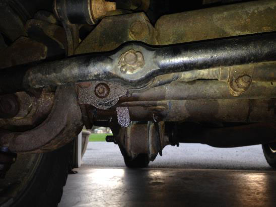
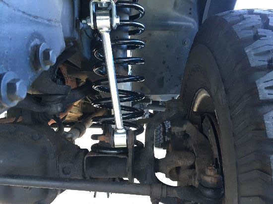
3. Using a 15mm socket (early models use a T50 Torx socket), remove bolt mounting the front track bar to the passenger’s side of the axle. Let track bar hang, save bolt and flag nut.
4. Raise front of vehicle with a hydraulic jack and place jack stands under the frame rails just behind the lower control arms.
5. Remove the front wheels
6. 1997 Model Only: Mark the position of the alignments cam adjusters at the front end of each lower control arm.
7. Support the front axle with a hydraulic jack. Remove shocks using a 13mm socket and wrench on the lower mounts, and a 15mm wrench at the stud. Use vice grips at the top of the stud or a strong clamp around the upper part of the shock to keep it from rotating. Save lower shock hardware.
8. Remove upper mounting nut (15mm) from front sway bar links. Disconnect links from sway bar using a small pickle fork and/or hammer to release the tapered seat.
9. Disconnect front sway bar link from the axle with a 19mm socket and T55 Torx socket (late models use a bolt with a serrated neck that keeps the bolt from rotating). Save axle mount hardware.
10. Remove cotter pin and castellated nut (19mm) from the drag link end at the pitman arm. Thread the nut back on a couple of turns. Strike the pitman arm and/or the end of the drag link to release the tapered seat. Take care not to damage threads or drag link end. Remove drag link end from pitman arm and let it hang. Save nut; discard cotter pin.
11. Remove driver’s side coil spring retainer clip bolt (13mm) located aft of the coil. Save clip and bolt.
12. Support axle with hydraulic jack. Loosen and remove driver’s and passenger’s side lower control arm bolts (21mm) at the axle. This allows the axle to lower enough to easily remove and install coil springs. Save control arm hardware.
13. Slowly lower the hydraulic jack, keeping mind not to overextend brake lines. Remove original coil springs. It may be necessary to relocate brake lines for coil spring removal—this requires a T40 Torx socket.
14. Remove factory bump stop from upper coil mount. Large pliers or channel locks can be used to pull it out. Remove factory bump stop retainer cup bolt (15mm) from center of retainer cup.
15. Install the provided 2” bump stop spacer between the factory retainer cup and the frame with a 10mm x 80mm bolt. Torque bolt to 30 ft-lbs. Reinstall factory rubber bump stop in the retainer cup.
16. Install the new coil springs and rotate the ends to seat in the axle mounts.
17. Raise axle until coils seat in upper mounts. Reinstall driver’s side coil retainer clip and torque to 20 ft-lbs.
18. Reattach driver’s and passenger’s side lower control arm bolts/nuts/washers. Do not tighten bolts completely and ensure washers are inside the cam stops on the axle. Lower control arm bolts will be torqued with the weight of the vehicle on the suspension.
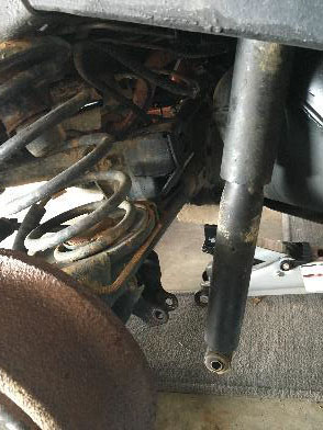
19. Install the new shocks with the provided upper bushings/hardware. Leave upper nut loose.
20. Attach shock to the axle at the bottom mount with the original hardware. Torque bolts to 20 ft-lbs. Tighten upper shock stem nut until the bushing begin to swell. Install thin jam nut and tighten against the first nut.
21. Locate the factory front track bar mount on the passenger’s side of the axle. Measure 3⁄4” toward the driver’s side from the center of the original mounting hole and drill a 13/32” hole at the mark through the front and aft faces of the mount. Do not install front track bar at this time.
22. Reattach drag link end to the pitman arm with the original castellated nut. Torque to 60 ft-lbs. Align cotter pin hole with slots on the nut and install the provided cotter pin. Never loosen nut to align cotter pin, only tighten.
23. Install provided sway bar link U-brackets to each end of the sway bar using 10mm x 40mm bolts, nuts, and 3/8” USS washers. Install the bolt up through the bracket and sway bar hole. Position the bracket so that the holes are facing the same direction as the hole on the axle for the sway bar mount. Torque bolt to 40 ft-lbs.
24. Locate the new front sway bar links and install hourglass bushing with light grease. The front sway bar links have offset eyes. Install a smaller (5/8” OD x 0.407” ID) steel sleeve in one end and a larger (5/8” OD x 0.480” ID) steel sleeve in the other end of each link.
25. Install the new front sway bar links to the axle mount with the factory hardware and to the U-bracket with 3/8” x 2-1/2” bolts, nuts, and washers. The smaller ID end of the link will mount to the U-bracket. When mounted correctly, the links will taper in toward the center of the vehicle (running from axle to sway bar). Torque factory hardware to 55 ft-lbs and 3/8” hardware to 30 ft-lbs.
26. Install wheels and torque lug nuts to manufacturer’s specifications.
27. Remove jack stands and lower vehicle to the ground.
28. Bounce the front of the vehicle to settle suspension.
29. Connect front track bar to newly drilled hole in the axle mount. Torque to 55 ft-lbs. It may be necessary to turn the steering wheel to assist in aligning track bar with hole.
30. Torque lower control arm bolts to 85 ft-lbs. 1997 Models only: be sure to align marks made at step 6 before torqueing.
31. Check all hardware for proper torque.
Rear Installation
1. Disconnect the rear track bar from the passenger’s side frame mount with a 15mm socket and an 18mm wrench. Save hardware.
2. Raise the rear of the vehicle with a hydraulic jack and place jack stands underneath the frame rails just forward of the lower control arm mounts.
3. Remove the rear wheels.
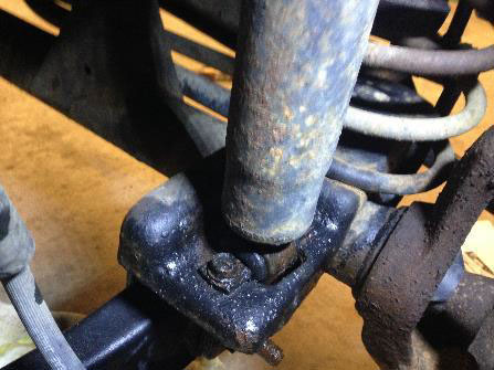
4. Support the rear axle with a hydraulic jack. Remove the shocks using a 13mm socket on the upper mounts and a 15mm socket and 18mm wrench on the lower mount. Save all hardware.
5. Disconnect the rear sway bar links from the sway bar and frame using a 15mm socket and 18mm wrench. Save all hardware.
6. Lower the rear axle with the hydraulic jack and remove the coil springs.
7. Remove the factory bump stop from the upper coil mount. Large pliers can be used to pull it out. Remove the factory bump stop retainer cup by removing the bolt (15mm) from the center of the retainer cup.
8. Install provided 2” bump stop spacer between the factory mount retainer cup and the frame with a 10mm x 80mm bolt. Torque to 30 ft-lbs. Reinstall factory rubber bump stop in the retainer cup.
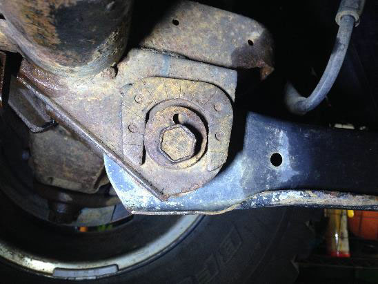
9. Remove plastic cover from the track bar mount on the driver’s side of the axle. Discard cover.
10. Disconnect the rear track bar from the axle using a T55 Torx socket. Remove track bar, but keep note of how it is positioned in the vehicle. It will be reinstalled later. Save all hardware.
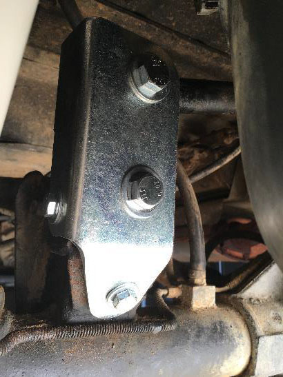
11. Position the provided track bar relocation bracket on the rear track bar axle mount. Install provided 3⁄4” OD x 9/16” ID x 1.58” crush sleeve in the original track bar mount point. Install provided 12mm x 80mm bolt and 7/16” washer through bracket, factory mount, sleeve and out through the forward side of the axle mount. Loosely fasten with the factory flag nut. If flag nut is damage, use provided 12mm nut.
12. With the new bracket in place as a guide, mark the three holes to be drilled. The bottom hole is 3/8”, the top and driver’s side hole are 5/16”. Fasten the bracket with the provided 3/8” x 1” bolt, nut, and washers in the bottom hole and the 5/16” x 1” bolts, nuts, and washers in the top and side holes. Torque 3/8” bolt to 30 ft-lbs, and the 5/16” bolts to 22 ft-lbs. Torque 12mm main bolt to 60 ft-lbs.
13. Install the factory rear track bar in the new relocation bracket with the provided 12mm x 80mm bolt, nut, and 7/16” washers. The bolt must be installed aft to front. Leave bolt loose.
14. Install the new coil springs. The springs can mount in either direction, on either side.
15. Lightly grease and install the hourglass bushings and steel sleeves into the rear shock eyes.
16. Attach new shocks to the frame with the original hardware. Torque bolts to 20 ft-lbs.
17. Raise the rear axle to meet the lower shock mounts. Install lower shocks using original hardware. Torque to 55 ft-lbs.
18. Locate provided rear sway bar links with preinstalled bushings. Install provided 5/8” OD x 0.407” ID steel sleeves in each link end.
19. Install rear sway bar links to the original frame mounts and the sway bar with provided 10mm x 60mm bolts, nuts and washers. Torque to 30 ft-lbs. Factory flag nut can be used on the frame mounts.
20. Install wheels and torque lug nut to manufacturer’s specifications.
21. Remove the jack stands and lower the vehicle to the ground. Guide rear track bar into place while lowering vehicle to the ground.
22. Bounce the rear of the vehicle to settle the suspension.
23. Reattach the rear track bar to the passenger’s side mount with the original hardware. Torque both mounting bolts to 70 ft-lbs.
24. Check all hardware for proper torque.
Transfer Case Drop
1. Locate and loosen 4 nuts (13mm) mounting the transmission to the transfer case skid plate. Do not completely remove nuts.
2. Support skid plate with a hydraulic floor jack.
3. Loosen, but do not remove all six skid plate mounting bolts.
4. Remove three passenger’s side bolts and slowly lower the skid plate from the frame just enough to install the provided spacers between the frame and the skid plate. Remove any rust so the spacers will fit flush against the frame. The hollow side of the spacer should be facing up.
5. Attach the skid plate to the frame with the provided 1⁄2” x 2 1⁄2” bolts, 7/16” USS washers, and conical washers (with the point of the conical washer facing up and contacting the bottom of the skid plate). Leave hardware loose.
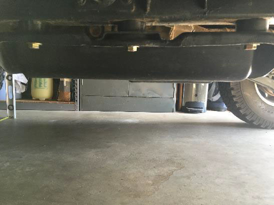
6. Repeat procedure on driver’s side. Torque all skid plate bolts to 65 ft-lbs.
7. Torque transmission mount nuts to 18 ft-lbs.
Post-Installation
1. Check for adequate clearance between all rotating, mobile, fixed, and heated components. Verify clearance between exhaust, fuel lines, brake lines, fuel tank, floor boards, wiring harness, and steering components.
2. Perform steering sweep, checking brake hose slack and that moving parts do not make contact with anything to include heated members, brake hoses, or other moving parts.
3. A front end alignment is required to adjust toe-in setting as well as to straighten the steering wheel. Caster can be adjusted on 1997 models using the factory alignment cam bolts.
4. Check all hardware for proper torque after 500 miles. Check hardware at scheduled maintenance intervals. Installation Instructions Written by ExtremeTerrain Customer Trey Clarke on 11/24/2015
