FREE 1 to 3-Day Delivery on Orders $149+ Details

How to Install a Tuffy Dark Slate Security Console w/ electronics mounting bracket & 12V power
Installation Time
30 minutes
Tools Required
- 18MM Socket and ratchet (To remove seats)
- 13MM Deep well socket, long extension, and ratchet (To remove and fasten emergency brake
- T-20 Torx bit or wrench (To remove OEM console)
- T-30 Torx bit or wrench (To remove OEM console)
- Flat Head Screwdriver (If OEM console has electric window switches in the rear)
- Phillips head screw driver (Short)
- 3/8” Nut-driver and/or wrench
- 5/16” Nut-driver and/or wrench
- 11/32” Nut-driver and/or wrench
- Electrical wire cutting, stripping, and crimping tool (For 12 volt outlet installation)
- Electrical volt meter (For 12 volt outlet installation)
- Electric drill
- 3/8” Drill bit
- Marker or pencil
- Silicone sealant (Recommended)
- ½” Socket and ratchet
- ½” Wrench
Shop Parts in this Guide
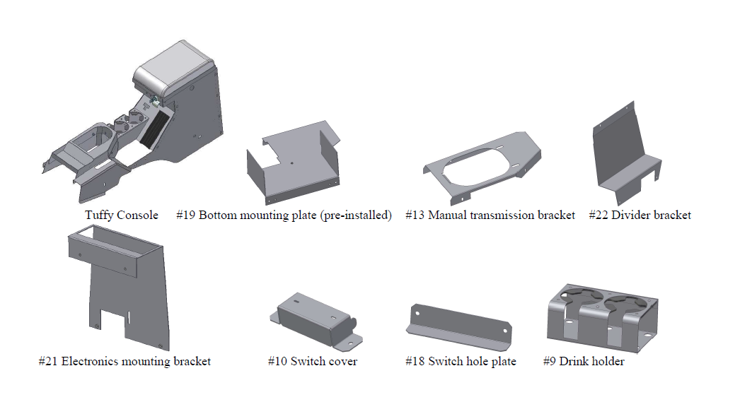
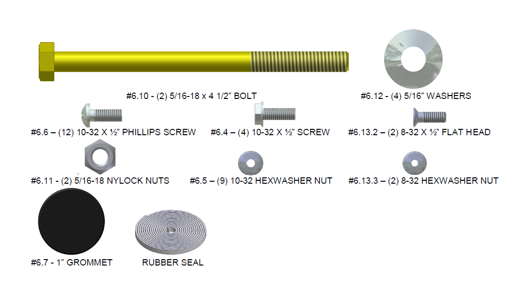
PARTS CHECKLIST
SHIPPING PACKAGE CHECKLIST
ATTENTION:
THIS CONSOLE WAS DESIGNED FOR A STOCK OEM VEHICLE, ANY MODIFICATIONS MADE MAY AFFECT THE FIT INCLUDING: CARPET REMOVAL/CHANGES, LIFT KITS, SEATS, ETC.
FREQUENT LUBRICATION IS NECESSARY ON THE LOCKING SYSTEM - The pushbutton lock contains an “O” ring seal to protect the interior from dust and water. If this mechanism is not lubricated regularly it will become difficult to operate and it may not return to its home position preventing the key from operating the lock. If this happens simply pull up on the pushbutton to manually bring it back to its home position. Lubricate the pushbutton with a light lubricant such as silicone spray. The pushbutton may have to be periodically disassembled and cleaned.
PLEASE READ ALL INSTRUCTIONS THOROUGHLY BEFORE STARTING INSTALLATION.
1. IMPORTANT! Make sure the vehicle is parked on a flat surface and place stops behind the wheels to prevent it from rolling. During the installation the vehicle will need to have the emergency brake deactivated, and the 4wd transfer case, Automatic, and manual transmission placed in neutral.
2. The installation will be much easier if the passenger side and/or drivers side seat(s) are unfastened by removing the (4) mounting bolts per seat (Slide the seat forward and reverse for access to bolts). Leave the seatbelts attached and wiring but maneuver the seat to the side making more room for the console removal and installation. The wiring harness may come unplugged (Especially on the driver side); don’t forget to reattach it when refastening the seats or the Jeep will beep constantly.
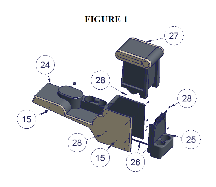
3. On the OEM console detach the original insert (#27 - Fig 1) by removing the (4) original torx mounting screws (#15 – Fig 1, these will be reused) and (10) original torx side screws (#28 – Fig 1, these will not be reused). Some of these torx side screws may instead be push fasteners which can be removed with pliers.
4. Maneuver the original insert (#27 – Fig 1) out of the original console (#24 – Fig 1) by popping it down and out of the tabs on the inside top front of the original console. If the vehicle has electric window switches in the rear panel follow the below instructions to remove the original insert.
If the vehicle has electric window switches mounted in the rear panel: (#26 – Fig 1)
5. Vehicles with rear electric windows which have switches mounted in the rear panel (#25 – Fig 1) with a wiring harness (#26 – Fig 1) will need them removed. Unfasten the (4) original torx screws (#28 – Fig 1, These are accessed behind the OEM console sides and will not be reused). Detach the original rear panel from the insert (#25 – Fig 1).
6. Then unplug the switch harness and remove the switch from the rear panel.
7. Remove the support clamps which attach the wiring harness to the bottom of the original insert (#27 – Fig 1) by popping them out with a flat head screwdriver. (These may break when removed but they will not be reused).
8. Maneuver the original insert (#27 – Fig 1) out of the original console (#24 – Fig 1) by popping it down and out of the tabs on the inside top front of the original console.
9. Remove the harness plugs (#26 – Fig 1) where they are connected to the underside of the main console (#24 – Fig 1). This can be done by sliding the harness plugs off the retaining clip or completely popping the clip out. Be careful, the pop-in clip has a weak
attachment to the harness plug and when it is popped out, if the harness plug is used for leverage, it can be damaged. (This pop-in fastener will not be reused)
10. Unplug the harness (#26 – Fig 1) which should completely disconnect it from the vehicle. Set it aside it will be reused.
11. Place the 4wd transfer case shifter in neutral and remove the shifter knob. Remove the knob by pulling it straight off with moderate force. It is not screwed on, do not try to twist and be careful what is behind you because when it comes off you may fly backwards.
12. Pop the rear portion of the darker top plastic skin away from the lighter main original console by hand (#24 – Fig 1) to expose the emergency brake assembly. It will not come all the way off because of the emergency brake.
13. Unfasten the (4) mounting nuts securing the emergency brake to the floor plate. Completely remove the front (2) nuts but leave the rear (2) nuts on a few turns. As an alternative the emergency brake cables could be unhooked with the correct tools and skills. Be sure vehicle will not roll.
14. If the vehicle has a manual transmission pop the rear end of the shift boot out of the original factory console then slide the front tabs out from under the lip on the original console.
15. Completely remove the original factory console. Placing the transmission in neutral will make this easier. Lift the rear up first then maneuver the front off of the emergency brake and levers. Be sure vehicle will not roll.
16. Refasten the (4) original nuts on the emergency brake assembly. (or reattach cables)
17. Pre-wire for the 12 volt electrical outlet. ATTENTION! This should be done by a skilled professional. Tuffy does not warranty any electrical components or damage caused by them. Improper installation can cause damage to the vehicle and/or any electronics plugged into the outlet. Make sure there is no power to the wiring when installing.
18. Locate a 12 Volt 15 Amp rated power source. Make sure it is only live when the ignition is on so unwanted battery run down is avoided when the vehicle is not running.
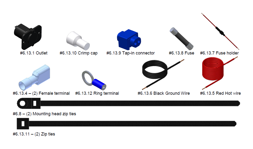
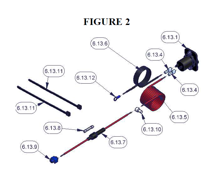
19. Attach the Fuse holder (#6.13.7 - Fig 2) to the Red (Hot) wire (#6.13.5 – Fig 2) using a provided Closed end crimp cap connector (#6.13.10 – Fig 2).
20. With the power supply off attach the other end of the Fuse holder (#6.13.7 - Fig 2) to a power source using the tap-in squeeze connector provided (#6.13.9 – Fig 2). Make sure this fuse holder is easily accessible for replacement.
21. Attach the Black (Ground) wire (#6.13.6 – Fig 2) to the provided Ring terminal (#6.13.12 – Fig 2) then fasten it to an adequately grounded bolt/surface on the console base plate mounted to the vehicle floor.
22. Use the provided zip ties (#6.13.11 – Fig 2) to support the wires and make sure there is no potential for damage caused by sharp edges. Cut the wire to the correct length where the outlet in the console will be located and install the crimp on flat
female terminals (#6.13.4 – Fig 2) on the end of the Red (Hot) and Black (Ground) wires.
23. Install Fuse (#6.13.8 – Fig 2) in Fuse holder (#6.13.7 – Fig 2).
24. Using a volt meter test that there is 12 volt power to the Red (Hot) wire and that the Black (Ground) wire is properly grounded. Turn off power when complete.
If you are installing a Stereo, CB, or other electronic equipment in the console:
25. Run all the required stereo and speaker wires to the console mounting location. Tuffy recommends running wires in a protective wire loom and using rubber grommets when passing through any drilled holes. ATTENTION: Refer to your electronics
owner’s manual for instructions on how to mount and wire your electronics.
Stereo mounting note: If a stereo is to be mounted in the console an antenna extension wire will be required and is available at most stereo equipment stores.
CB mounting note: Tuffy recommends mounting an external CB speaker. These are available at most electronics supply stores.
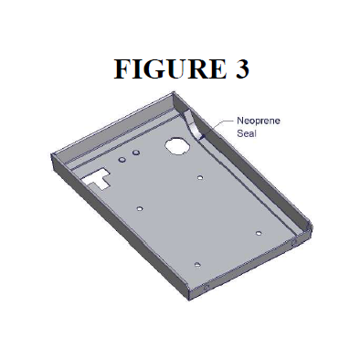
26. Install the rubber seal around the inside perimeter of the lid on the flat surface. (Fig 3)
27. Check the lock and latch operation on the Tuffy console.
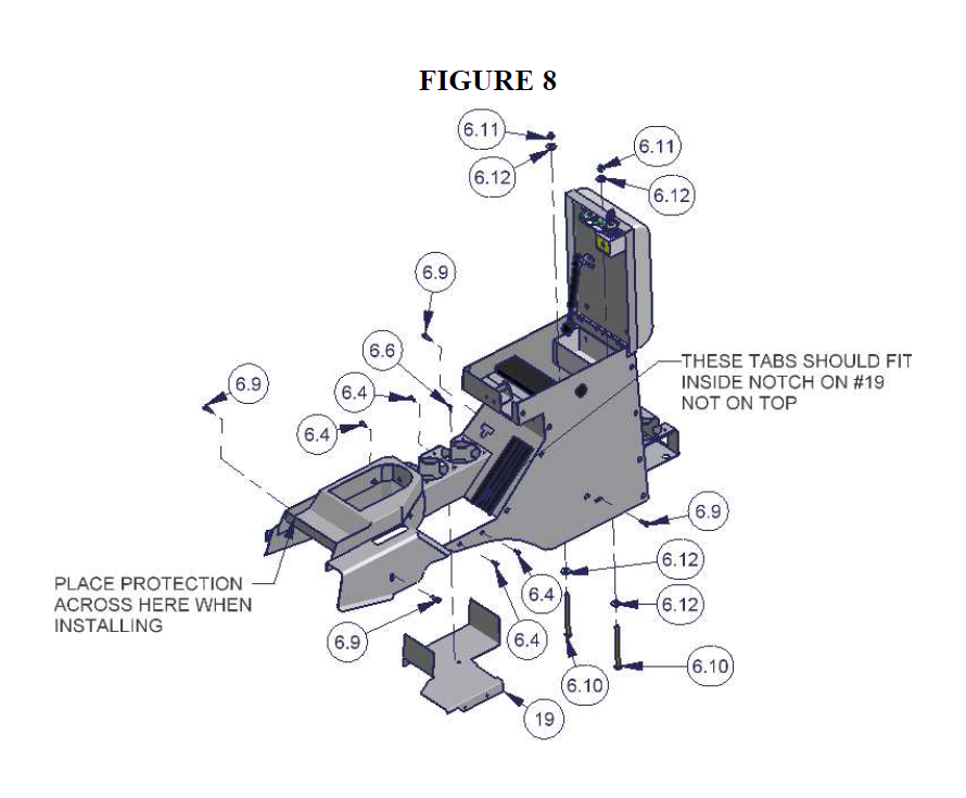
28. The #19 Bottom mounting plate is fastened to the console at the factory to prevent shipping damage. This plate must be removed for installation then it will be refastened later. (See Figure 8)
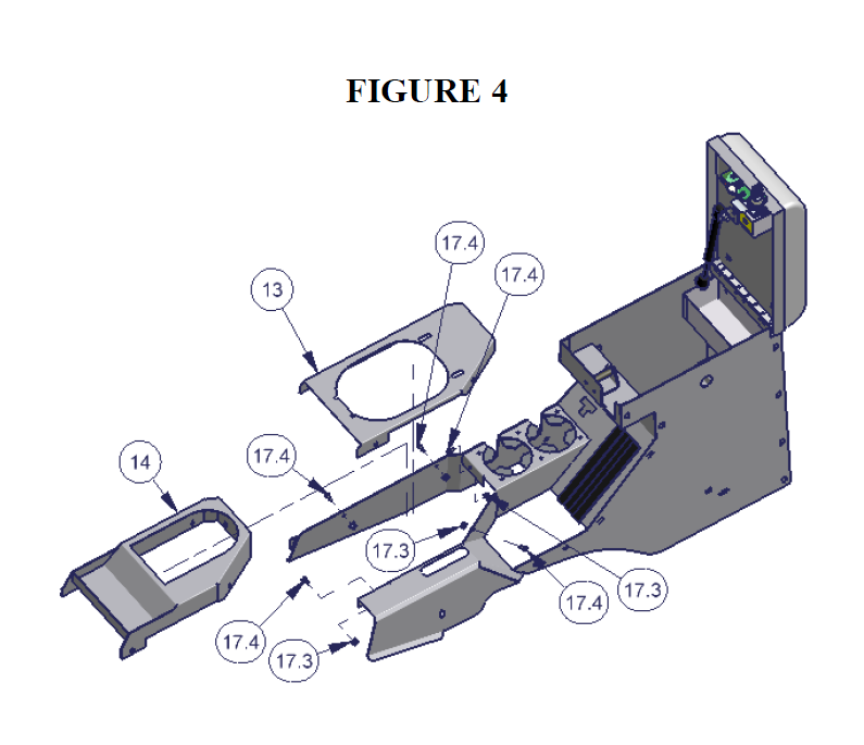
29. If you have a manual transmission the automatic transmission bracket (#14 – Fig 4) will need to be un-fastened and removed from the Tuffy console and the Manual transmission bracket (#13 – Fig 4) will need to be installed in its place.
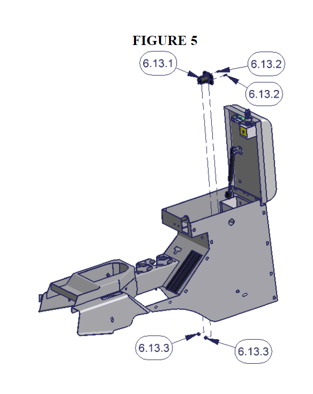
30. Fasten the 12 Volt outlet (#6.13.1 – Fig 5) in the console. Make sure it is oriented so the cover opens hinging up. Make a note of which terminal is positive and negative. When the wires are hooked up it will be difficult to see the emblems.
If a Stereo, CB, or other electronic equipment will be mounted in the console:
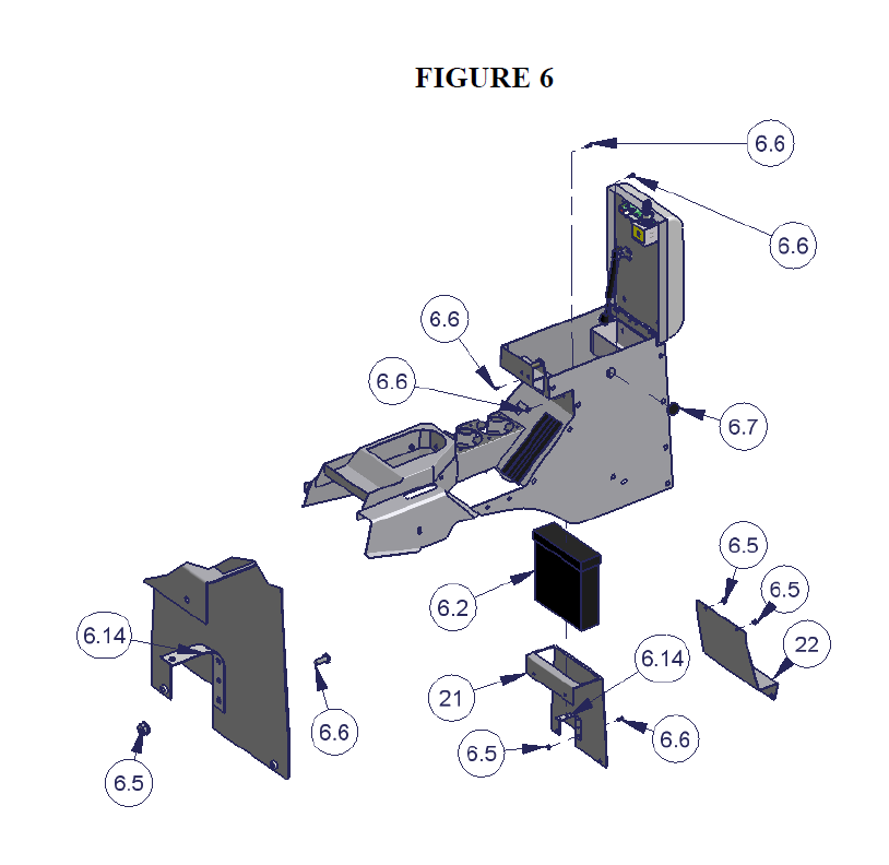
31. Install the electronics (Illustrated #6.2 – Fig 6) in the Electronics mounting bracket (#21 – Fig 6) by using the stereo support strap included with your stereo or CB (Illustrated #6.14 – Fig 6). (If you do not have a stereo support strap, plumber strap may be substituted.) Be sure the body on the electronics is not extending more than 7 13/16” behind the Electronics Mounting Bracket or it will hit the emergency brake assembly.
32. Install the Electronics mounting bracket (#21 – Fig 6) in the console. Check to make sure the lid will still close and latch without causing any problems.
NOTE: You may want to leave the mounting hardware loose for this bracket; it can make installation easier in a later step to unfasten this bracket and gain access under the console (The bracket cannot be removed completely after the console is installed but it can be loosened and moved to the side).
33. If electronic equipment will not be installed using the Electronics mounting bracket (#21 – Fig 6) install the Divider bracket (#22 – Fig 6).
34. Install the rubber grommet to plug the hole in the left side of the console. (#6.7 – Fig 6) If you are mounting a CB inside the console you can cut cross slits in the grommet to run the Mic outside the console.
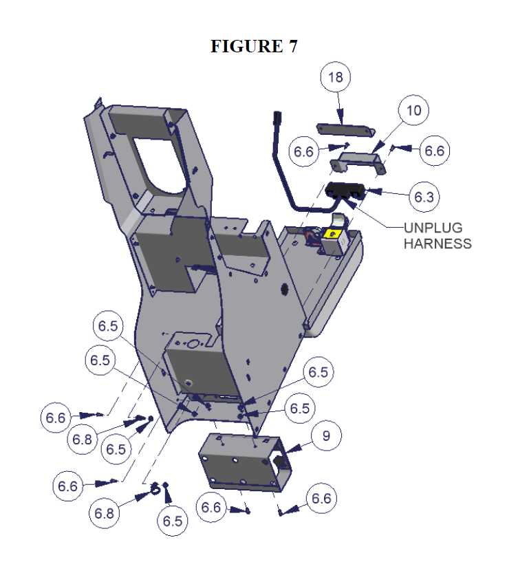
35. If the vehicle is not equipped with the electric rear window switches (#6.3 – Fig 7) then install the Switch Hole Plate (#18 – Fig 7).
36. If the vehicle is equipped with the electric rear window switches (#6.3 – Fig 7) install them in the Tuffy console using the provided Switch Cover (#10 – Fig 7). Make sure the tabs on the top and bottom of the switches are inserted in the corresponding slots in the Switch cover and console.
37. If the vehicle is equipped with the electric rear window mounting switches (#6.3 – Fig 7) plug the original factory harness into the switches which were previously mounted in the console. Then support the wiring harness by attaching the Mounting Head zip ties (#6.8 – Fig 7) to the wiring harness then fastening them to the holes in the Tuffy console.
38. Install the rear drink holder (#9 – Fig 7).
39. Place the Tuffy Bottom Mounting plate (#19 – Fig 8) in the vehicle under the emergency brake handle.
40. Make sure the 4wd transfer case shifter is in neutral, the transmission is in neutral, and the emergency brake is activated (pulled up). Be sure vehicle will not roll.
41. Put a protection barrier (like cardboard) between the bottom of the vertical plastic dash console and the front of the Tuffy console when installing to prevent scratches on the dash. (See Fig 8)
42. Insert the console into the vehicle by maneuvering it over the shift levers, the emergency brake, and the Bottom bracket (#19 – Fig 8). Be careful not to scratch the plastic dash or tear the seats. This is best done from the rear seat with two people.
OPTIONAL ADDITIONAL SECURITY STEP
43. Place the Tuffy console in the finished mounting position by lining up all (4) mounting holes on the sides then mark at least one spot on the vehicle floor under the 3/8” holes in the bottom of the Tuffy console for drilling. (For bolts #6.10 – Fig 8)
WARNING! Make sure that there is nothing under/on the vehicle that will be damaged by the drill bit when drilling.
44. Remove the Tuffy console and drill a ¼” pilot hole in each marked spot then drill them out to 3/8” holes. Use touch up paint or silicone sealant in any drilled holes to prevent rusting.
45. Place the Tuffy console back in the vehicle. Put a protection barrier (like cardboard) between the bottom of the vertical plastic dash console and the front of the Tuffy console when installing to prevent scratches on the dash. (See Fig 8)
46. Check the height on the Automatic shift bracket (#14 – Fig 4). The front of the console should sit flush on the base of the 4wd transfer case shifter and flush on the Automatic shift bracket. Adjust as necessary. The mounting holes for the Automatic shift bracket (#14 – Fig 4) are obrounded for adjustment. It is possible to slightly undo the mounting screws #17.4 – Fig 4) and then use a rubber mallet to force the bracket to the desired position but if the screws are loosened too much the nut on the backside will not catch when re-tightening the screw.
47. Prop the rear of the console up 3-4”. This will make access underneath easier.
Note: The previously installed electronics mounting bracket (#21 – Fig 6) or divider bracket (#22 - Fig 6) can be un-fastened and moved out of the way to improve access for the following steps (It cannot be completely removed at this point).
48. With the power turned off connect the Red (Hot) wire terminal (#6.13.4 – Fig 2) to the corresponding “ ” terminal and the Black (Ground) wire terminal (#6.13.4 – Fig 2) to the “-“ terminal on the back of the 12 volt outlet (6.13.1 – Fig 2) and test with a volt meter. The small bottom center connection inside the outlet should have power while the inside connection on the wall perimeter should be grounded. If this is not clear test an existing outlet in the vehicle and make sure it matches. Do not test power by plugging in electronics.
49. If you are installing electrical equipment inside the console connect all the wires according to the owner’s manual. Check to make sure the electronic equipment works correctly.
50. If the vehicle is equipped with the electronic rear window switches; plug the harness (#6.3 – Fig 7) back in and test the switches to make sure they work correctly.
51. Make sure all the wires and harnesses are fully protected and that nothing will damage them.
52. Fasten the Bottom mounting plate (#19 – Fig 8) to the Tuffy console. Be sure the tabs at the bottom of the emergency brake slot in the console are in the corresponding notch in the Bottom mounting plate and not on top of it (#19 – Fig 8). Start with the screw under the drink holder then install the other (4) after everything is aligned.
53. Remove any item propping the rear of the console up and start all (4) original OEM mounting torx screws through the holes in the sides of the Tuffy console (Illustrated #6.9 – Fig 8). Do not tighten them all the way. Then fasten the entire Tuffy console assembly down starting with the front driver side screw. Apply pressure to the left driver side of the console when tightening this screw to ensure the console is flush with the top of the 4wd transfer case shifter when tightened. (See Fig 8)
54. If the optional additional security steps were done fasten down the Tuffy console using the (2) 5/16-18 x 4 ½” Hex cap screws (#6.10 – Fig 8), (2) Hex nylon insert nuts (#6.11 – Fig 8), & (4) 5/16” USS washers (#6.12 – Fig 8) through the holes previously drilled. Do not over tighten.
55. Check the emergency brake, 4wd transfer case shifter, and Automatic or Manual transmission shifters. Check to make sure the console locks and functions properly.