 FREE 1 to 3-Day Delivery on Orders $149+ Details

How to Install Teraflex 6 In. Elite LCG Long Arm Suspension System w/o shocks on your 07-13 Wrangler
Tools Required
- 10mm socket/wrench
- 12mm socket/wrench
- 15mm socket/wrench
- 16mm socket/wrench
- 18mm socket/wrench
- 19mm socket/wrench
- 21mm socket/wrench
- 34" socket/wrench
- 3/8" socket/wrench
- 5/8" socket/wrench
- 7/8" socket/wrench
- 7/16" socket/wrench
- 9/16" socket/wrench
- 11/16"
These instructions apply to the following kit part numbers
Part #1257600 6” JK LA System w/shocks
Part #1457600 6” JK LA System w/no shocks
Kit Includes:
6” coil springs
6” Shocks (1257600 only)
Front sway bar links
Rear sway bar links
Long front lower control arms
Long front upper control arms
Long rear lower control arms (side specific)
Long rear upper control arms
Frame brackets-2 front/2 rear
Front upper and lower bump stop extensions
Rear upper and lower bump stop extensions
Front spring spacers
Rear spring spacers and guides
Rear trackbar bracket
Rear adjustable trackbar
Front trackbar bracket and frame brace
Heavy Duty drag link and flip kit
Front adjustable Monster trackbar
Front and rear brake lines
Rear spring retainers
Read this first:
Installation of this kit requires removal of the factory control arm mounts from the frame. The preferred removal method is a combination of a zip wheel and plasma cutter, with some cleanup grinding required. The new brackets must be welded in place as part of the installation of the kit. If you are not properly equipped to safely do this level of fabrication and welding, please contact TeraFlex for the name of a qualified installer in your area. Plan to spend 20 or more hours for installation.
With proper patience and care it is possible to leave the fuel tank in place during this installation. The photos accompanying our installation guide show how to cut and remove the rear brackets without damaging the fuel tank.
To allow for full droop without exhaust modification, you will need to purchase a JE Reel front drive shaft, Part# 31JK-OE-42F.
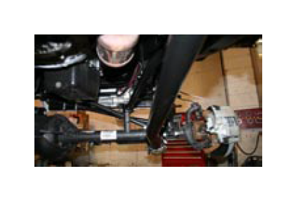
FRONT INSTALLATION:
1. Lift the vehicle and support under the frame so that the axles will be able to drop down far enough to remove and replace the coil springs. When placing supports under the frame, take into consideration the new brackets will be in a different location than the factory brackets and you may need to temporarily change the location of your frame supports because the area you will be working with in the rear is a large section of the frame.
2. Remove the tires.
3. Remove front transmission skid plate for driveline clearance.
4. Remove the front sway bar links.
5. Remove the clips that secure the ABS wiring harness to the brake line and disconnect the wire connecter behind the spring tower. Secure the lines temporarily to the axle in a position that will be safe for them through the rest of the install.
6.Remove the front brake calipers and hang them off the frame.
7.Remove the front lower control arms.
8.Remove the front upper control arms. On the passenger side it will be necessary to cut the bolt for the upper arm on the frame side. This will allow you to get the bolt out without removing the exhaust.
9.Support the axle and remove the front shocks.
10.Lower the front axle to make more room for working on removing the front upper and lower control arm mounts.
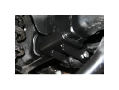
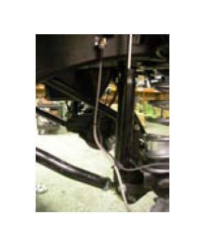
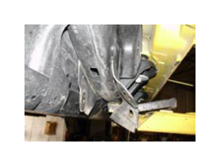
11.Use a plasma cutter, oxy/acetylene torch or zip cutoff wheel to remove just the front bracket. Be very careful to avoid undercutting into the frame. Use the following photos to determine where to cut.
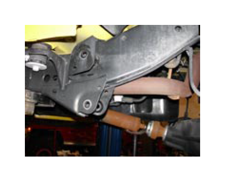
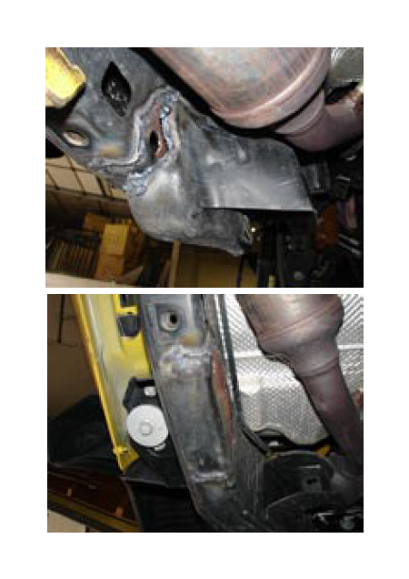
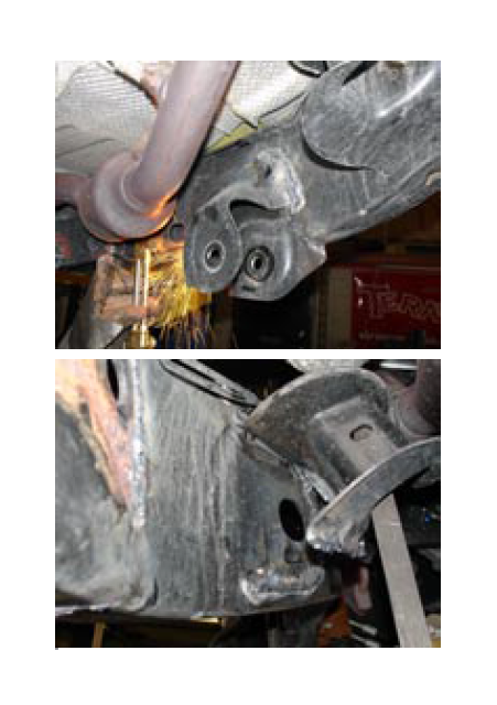
12.Remove both front upper and lower brackets and grind the remaining weld smooth with the frame in preparation for installing the new combination front bracket.
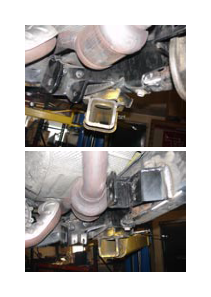
13.The new front bracket mounts to the cross member bolts, and the transmission skid plate hole is used to help locate the bracket (some models may not have threads in this frame hole because not all models come with the factory skid plate). Push the new bracket up tight against the frame. Mark the frame and the bracket so you will know were the bracket contacts the frame.
14.Remove brackets for welding prep. Clean all marked areas. Make sure there is no paint or any other possible contaminants like grease or rust.
15.Reinstall the brackets, make sure the bolts to the cross member are tight and the very front edge of the bracket is touching the frame. If you have the tranny skid plate bolts, install them at this time. Fully weld the front long arm brackets to the frame.
16.After the welds have cooled, clean the frame and brackets. Paint over welds and any other raw metal areas left from grinding and sanding.
17.Install the front lower arms with the rubber bushing at the frame end and the angled modular urethane joint at the axle end. The arm is bent for tire clearance so make sure the bend goes in toward the center of the jeep. Position grease zerks for access and where they will be most protected from rocks or other damage. Set front lower arm length to 34 3/16”.
18.The front upper arms require lifting the engine about one inch to get the provided 9/16”x3” bolt in on the frame side. The engine mounts are slotted, making it so that you can loosen the two main bolts and lift the engine about an inch. Use the bottom of the two holes for most applications. Position grease zerks for access and where they will be most protected from rocks or other damage. Set front upper arm length to 28 1/16”.
19.Remove the factory trackbar bolt on the frame side using a 21mm wrench, to hold the nut on the backside, a 21mm socket, and an impact gun. With the impact gun and socket remove the axle side. There should be a nut on the backside with a small tab that will hold it so you do not need a wrench on it. Once bolts are out, remove the track bar.
20.Remove the two lower bolts for the steering box with a 18mm socket and impact gun.
21.Slide the new track bar bracket over the factory bracket. Use the steering box bolts to hold the bracket; start the threads, but do not tighten them. Install the 1/2” button head bolt from the inside of the factory bracket through the TeraFlex track bar bracket so the head of the bolt is on the inside.
22.Place the brace with the fixed end in the factory trackbar bracket and the bend upward. Use the 9/16” bolt to hold it in place. Do not tighten at this point.
23.Hold the bracket for the brace up against the frame on the passenger side directly across from the factory trackbar bracket. Then hold the brace up in place to make sure you have lined it up in the proper location. When the desired location is established mark the frame in the area you plan to weld.
24.Remove the brace and bracket for welding prep. Clean the frame and bracket make sure you clean all surfaces that you will be welding. Clean surfaces are critical for a good weld.
25.Reinstall the bracket and the brace. Adjust the brace so it fits with bolts in each end.
Make sure the bracket fits the frame and is in the proper location. Tack two or three places to keep the bracket from pulling during final welding. Remove the brace and then final weld the rest of the bracket. A professional certified welder is always a good way to go if you have any doubts about your welding ability.
26.Clean all welded surfaces with a wire brush or something similar that will remove the dust in all the small grooves of the weld. Remove any paint that has been damaged from the heat created during the welding process.
27.Prime and paint all welded or raw areas.
28.Tighten the bolts that go in the steering box and the 1/2” button head bolt.
29.Install the brace and tighten the blots and jam nut. Use a 1 1/4” wrench for the jam nut.
30.Install the monster track bar with factory hardware.
31.Adjust the track bar so the axle is centered under the vehicle. From center to center of the joint should be close to 32 3/4”(with a 6” lift). Tighten the bolts on the adjuster sleeve.
Install front bump stop extensions
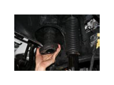
32.Remove the factory upper bump stop from the cup on the bottom of the coil tower.
33.Remove the front upper spring isolator.
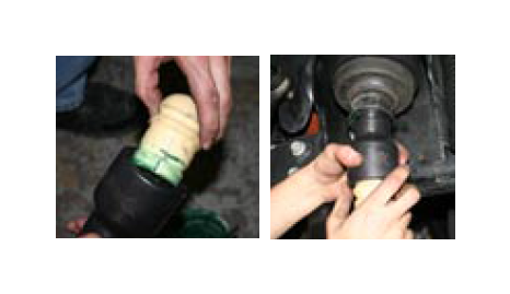
34.Install the new front spring spacer.
35.Reinstall the factory spring isolator below the new TeraFlex spring spacer.
36.Install the new upper bump stop extension by putting some grease on the upper part of the spacer and popping it into the bump stop cup.
37.Insert the factory bump stop into the bottom of the new bump stop extension.
38.Install the front lower bump stops by locating the center of the spring pad on the axle and drilling a 5/16 hole, then use a self tap bolt or a hand tap to create 3/8 coarse threads in the pad. Install the lower bump stops on each side with the 3/8 self tap bolts in the hardware kit.
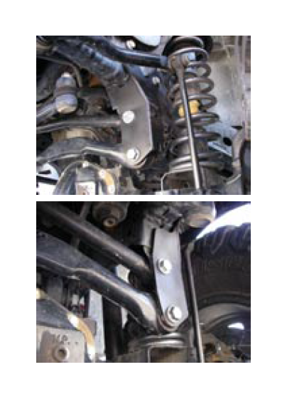
39.Install the new front springs. Using a coil spring compressor can make this easier.
40.Install the new front shocks.
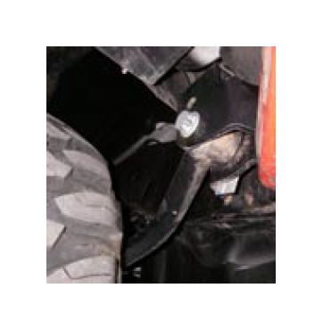
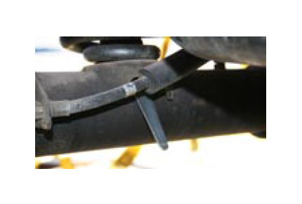
41. Install the front sway bar quick disconnect links.
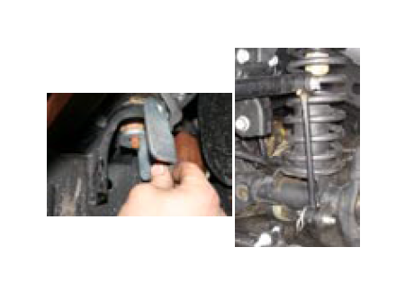
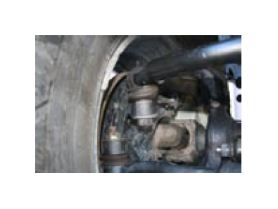
NOTE: On JK models with the factory disconnect front sway bar it is not necessary to install the QD brackets and pins on the front bodymounts. All other models install the brackets and pins where the sway bar links will be parked when disconnected, as shown in the photo.
42. The six-inch kit requires re-routing the front ABS lines. Route the line inside the frame rail and reconnect the line to the wheel speed sensor then zip tie or secure the line so it will be out of harms way. Make sure the line will not be pinched or smashed by any moving parts. Also make sure there is enough length for droop. Then repeat on the other side.
43.Remove the front factory brake lines and replace them with the new longer steel braided lines. 24 inch goes in the front.
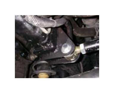
44.Remove the factory draglink at the steering knuckle. Loosen the adjuster sleeve and remove the long side of the drag link. The threads will be left hand so you will need to turn it opposite of way you might be used to. Install the new heavy flip drag link into the adjuster sleeve and set the length to 41 1⁄4”. The flip drag link is installed from the top down on the knuckle. To convert the taper, a sleeve is provided. To install the sleeve you must drill out the knuckle to a 13/16” hole. Drilling the knuckle straight is very important. After you have drilled the hole, install the sleeve, you may need to tap it into place, from the top down. Install the new heavy flip drag link. Use the provided washer and tighten the nut over the washer.
45.Reinstall the breather hose if it was disconnected during disassembly.
REAR INSTALLATION:
46.Now moving on to the rear, start by removing the tires if you haven’t done so already.
47.Remove the clips connecting the ABS lines to the upper arm mount on the axle side and the clips on the frame side directly above the arm.
48.Remove the bolt that holds the brake line to the frame. This will allow the axle to droop far enough to get your six-inch springs in.
49.Remove the rear upper and lower control arms.
50.Remove rear springs
51.Support the rear axle and remove the rear shocks.
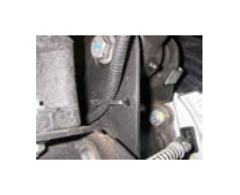
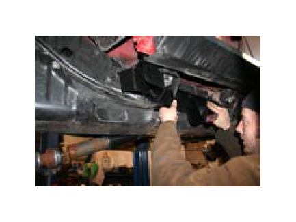
52.Remove the lower arm mounts from the frame. Be careful not to cut into the frame. First cut the passenger lower arm mount into sections. We recommend using a cut off wheel or zip wheel for this bracket because it will be easier to be precise in your cuts. Cut the bends of the bracket so the bracket will come off in three pieces. The middle piece should come off easily after these cuts have been made. Cut along the weld on the outside of the frame and remove the outer piece. Then begin cutting the inside bracket staying as close to the frame as possible.
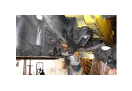
Be Very Careful Not To Damage The Fuel Tank!
On the rear most part of the bracket, the gas tank may be touching, so cut as much as you are comfortable with, then break the rest off so you don’t nick the tank. The upper on the passenger side is less critical, but if you use a torch or plasma cutter remember all the slag that goes over the frame could land on the gas tank. After removing all the rear control arm brackets clean off the leftover welds or material from the frame.
53.Install the passenger side rear bracket first. This bracket uses one of the gas tank skid plate bolts. Loosen the gas tank skid plate bolts and lower the skid plate just enough to get the bracket between the frame and the skid plate. Line up the bolt hole and mark the frame and the bracket for welding preparation. Then remove the bracket and clean the paint from all marked areas. Reinstall the bracket, tack into place, and then fully weld.
On the driver side hold the bracket into place. There is no hole to match up the to on the frame so the exact location should be determined by measuring the other side and matching the driver side to it. Mark the bracket and the frame for welding preparation. Remove the bracket and clean off the paint from the bracket and the frame in all marked areas. Reinstall the bracket and tack into place. Check the passenger side to make sure you are in the right place and fully weld.
54.Clean all welds and any raw metal areas. Then prime and paint them.
55.Install rear upper arms with factory hardware on the axle side and the provided 9/16”x 3” bolt on the frame side. Make sure the bend goes in away from the tire. The fixed end goes to the frame and the adjustable end goes to the axle. Set the rear upper arm length to 20 9/16”.
56.Install the rear lower arms with the rubber end at the frame side and the flex joint at the axle and the bend is supposed to go up and in towards the center of the vehicle. Place grease zerks so they are accessible and out of harms way. Do not fully tighten the rubber end at this time. Set rear lowers to 36 1/8”.
57.Remove the rear track bar.
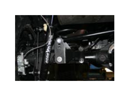
58.Install new rear trackbar bracket. The rear lower control arm bolt and the new U-Bolt brace the rear trackbar bracket. Remove the rear lower control arm bolt. Place the bracket into position and reinstall the bolt. Use the provided bolt 3 1⁄2” x9/16” in the bracket going through the factory bracket also use the provided sleeve in the factory bracket to keep the bracket from crushing.
59.Install the U-bolt.
60.Install the new adjustable trackbar using the factory fasteners. Set trackbar to 40 1⁄2”.
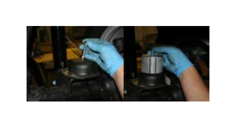
61.Install your new rear spring spacer/ guides. They pop into the hole in the middle of the spring bucket. It helps to put some grease on the part and the frame. Then pop your factory isolator onto the spring guide.
62.Install your new six-inch springs.
63.Install lower spring retainer. The lower spring retainer has a special tool that comes with it. This tool will make it easier to get the nut up under the lower spring mount. Place the nut in the tool and then work it up under the front side of the mount so you can see the threads of the nut through the hole in the mount. Place the spring retainer plate on the mount and put the bolt and lock washer through the plate into the nut and tighten it down.
64.Install new sway bar links. Mount the sway bar links so they are on the inside of the sway bar and on the inside of the axle mount. This will give you the best tire clearance.
65.Install new shocks.
66.Remove the factory rubber brake lines and replace them with your new steel braided brake lines. Anchor the new rear brake hoses with the angle brackets and clips provided in the hardware kit.
67.Remove the rear factory bump stop cushion from the cup in the frame. The TeraFlex upper bump stop extension goes into the factory location. Pop it into place then pop the factory cushion in the TeraFlex extension.
68.Install the rear lower bump stop extension. Use the 5/16” X 1 1⁄4” bolts to fasten them into place. Make sure they are in the right way. The rear bolt head should be visible if you where looking strait down on it and the front should be covered by the over hanging edge.
69.Bleed the brakes being careful to keep fluid in the master cylinder at all times. Reinstall the axle breather hose if it was removed during disassembly.
70.Reinstall tires and wheels.
71.Set on the ground and torque all the control arm bolts, trackbar bolts, steering and lug nuts. Lock-Tight is highly recommended for all fasteners.
72.Secure the brake hoses and ABS wiring so they will not be damaged during vehicle operation.
73.Have the vehicle alignment checked and adjusted by a shop that is familiar with proper alignment settings on a lifted vehicle.
NOTE: Caster should be set at 5 degrees. The passenger side may need to be turned 1/4 to 1/2 a degree more to avoid pulling to the right while driving.
MAINTENANCE NOTE: grease all zerks every 3000 miles.
