FREE 1 to 3-Day Delivery on Orders $149+ Details

How to Install TeraFlex 4" Pro LCG Lift Kit w/Shocks on your 1997-2006 Wrangler

Shop Parts in this Guide
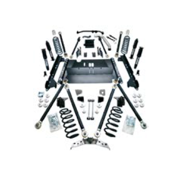
- Teraflex 4-Inch Pro LCG Long Arm Suspension Lift Kit with 9550 VSS Shocks (04-06 Jeep Wrangler TJ Unlimited)
- Teraflex 4-Inch Pro LCG Long Arm Suspension Lift Kit with 9550 VSS Shocks (97-06 Jeep Wrangler TJ, Excluding Unlimited)
- Teraflex 4-Inch Pro LCG Long Amr Suspension Lift Kit (97-06 Jeep Wrangler TJ, Excluding Unlimited)
- Teraflex 5-Inch Pro LCG Long Arm Suspension Lift Kit with 9550 VSS Shocks (97-06 Jeep Wrangler TJ, Excluding Unlimited)
- Teraflex 5-Inch Pro LCG Long Arm Suspension Lift Kit with 9550 VSS Shocks (04-06 Jeep Wrangler TJ Unlimited)
- Teraflex 5-Inch Pro LCG Long Arm Suspension Lift Kit (97-06 Jeep Wrangler TJ, Excluding Unlimited)
Take every precaution to make this installation a safe procedure. Make safety the number one priority with any suspension or lift installation.
Please make sure your kit includes the following items before starting installation:
Belly Up Skid Plate Adjustable front track bar
Shock kit Rear truss and hardware
4”or 5” spring kit with bumpstops Frame brackets
Front & rear upper arms w/hardware Hardware pack
Front & rear lower arms w/hardware Shock relocation brackets
Front & rear upper brackets Front exhaust pipe insert
Long Arm Kit
The 5” PRO-LCG has a new style track bar and mounting bracket and includes a brake line kit and transfer case lowering kit.
This kit is designed for the Jeep® TJ Wrangler, including Unlimited and Rubicon editions. It replaces the standard length control arms with new, longer lower control arms and 4-link upper control arms. Rear track bar is eliminated.
A trained and experienced suspension mechanic must install this kit. Modifications to the vehicle frame include removing factory brackets and welding on new mounting brackets. Also the muffler must be replaced with a smaller diameter muffler, and the tailpipe will have to be re-routed to clear the rear upper control arms. Safe operation of the vehicle requires that the installation be done correctly with careful attention to detail. Once the kit is installed, you will enjoy the comfort and flexibility that TeraFlex is known for. The kit will allow you to run much larger tires than stock while maintaining a low center of gravity.
Shift Linkage Plate
1. Use the supplied transfer case shift linkage plate (TJ Model 1997-2002) to lower the mounting point of the shift linkage. The bracket faces down with the supplied 1/4” bolts, and lock nuts securing the plate to the bracket.
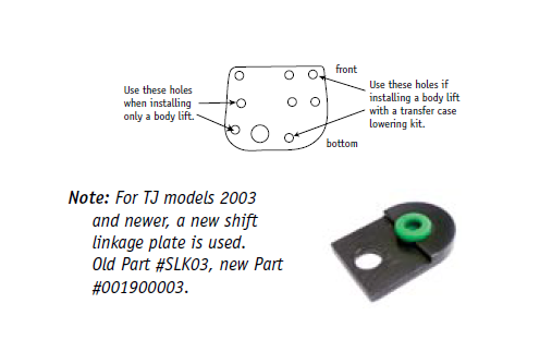
2. Re-attach the transfer case linkage bracket to the bottom of the tub. Attach the linkage with bracket to the transfer case.
3.To properly re-align the fan shroud it may be necessary to lower it one-inch to clear the fan blades. Re-drill new mounting holes in the shroud at the new position.
4.Re-attach fan shroud and check to see if fan can rotate without interference. Check all wires, hoses and fuel lines for clearance.
5.Check all bolts after the first 500 miles.
Preparation
6. Support the vehicle under the frame with the vehicle high enough that the axles can be fully drooped (for removal of factory coil springs and installation of the new TeraFlex coil springs).
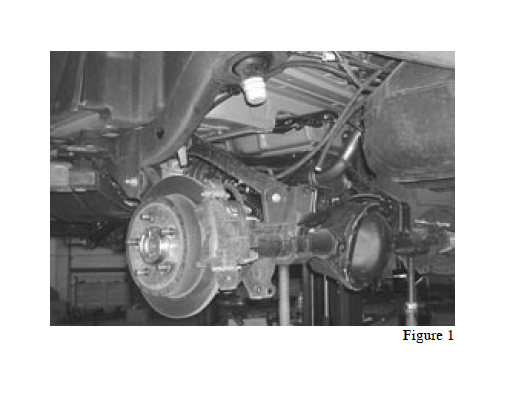
7. Remove tires, shocks, sway bar links, coil springs and upper & lower control arms. (Figure 1).
8. Support the transmission and remove the transfer case skid plate.
9. Hold up the exhaust patch that comes with the kit and mark the exhaust header pipe as shown. This exhaust patch is needed to provide clearance for the new longer front upper control arms and replaces the factory bend where the exhaust comes in front of the oil pan and heads back toward the catalytic converter.
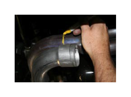
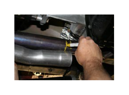
Cut the exhaust at your mark near the front corner of the oil pan, and remove the rest of the exhaust system including the catalytic converter, muffler and tailpipe. Be very careful to avoid damage to the oxygen sensor and wiring. Make the second cut on the exhaust
where you made the mark a few inches in front of the catalytic converter and reinstall the exhaust at step 25. When you have the new muffler and tailpipe built and installed, have the exhaust shop weld in the front exhaust patch.
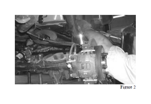
10. Carefully remove the front upper & lower and rear lower control arm mounts from the frame with a cutoff tool or torch. Be careful not to cut into the frame. (Figure 2)
Installation
11. A new one-piece bracket that includes mounting points for both front and rear lower control arms is included in the kit (old part #250L, 250R, new part #008002501, 008002502). The bracket slides up over the frame from the bottom and is located on the main frame rails by the factory skid plate mounting bolts. Once the brackets are installed, the factory skid plate mounting bolts (6 bolts) can be installed to hold the bracket .
12. Tack weld the bracket to the frame in 4 places laying about 1 to 1 1/2 inches of weld bead to secure the bracket to the frame. After welding, paint the weld area to prevent rust. This welding ensures the bracket will not move or work loose and allows removal of the skid plate for service without having to disassemble the suspension.
Note: Modifications to the factory skid plate will be required for rear control arm clearance if the TeraFlex Belly-Up skid plate is not installed. (Old Part #BUT-03, new Part #004648403)
Belly Up Skid Plate
13. Attach your new Belly Up skid plate to the frame by aligning the transmission bolts with the holes in the skid plate and then bolting the skid plate to the frame using the six factory skid plate mounting bolts.
14. Bolt the transmission mount to the skid plate using the factory nuts and the mounting holes in the center of the plate.
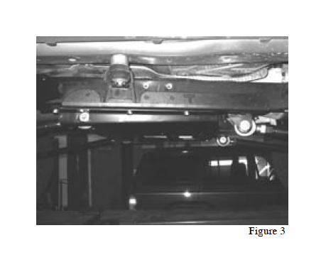
15. Figure 3 shows the main bracket installed with the arms and the TeraFlex Belly Up Skid Plate.
Note: To reduce rear driveshaft angle, install the 6 drop spacers and use longer bolts to install the skid plate. Check fan blade clearance after installing skid plate.
Rear Installation
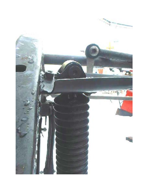
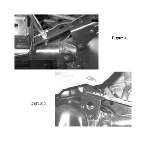
16. The rear upper control arms attach to the rear axle using an axle truss. The truss must be professionally welded to the axle tubes. Set the truss in place on the axle housing and mark where the truss contacts the axle tubes. Take the truss back off and clean any dirt, grease and paint off the tube to ensure a good weld. Set the truss back in place, route the breather hose through the hole in the truss, & bolt on the two angle brackets (Fig. 4 & 5). Leave the bolts on the angle brackets loose until the truss is located, then tack weld the truss to the axle housing tubes. Tighten the cover bolts and bracket bolts and final weld the truss to the axle tubes. Paint the welds to prevent rust.
Note: to avoid diff. cover leaks we recommend removing and resealing the cover with silicone as part of the truss installation.
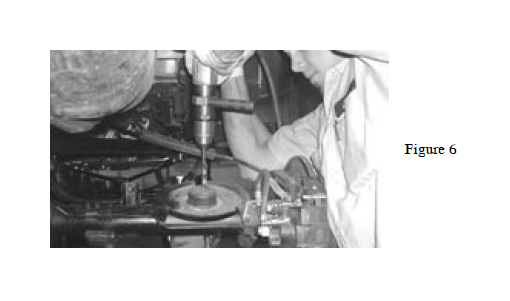
17. Using a 5/16” drill bit, locate the center of the lower spring pad. The divot in the center works well as a guide. Drill a hole through the guide in the pad.
(Fig. 6)
18. Using the aluminum spacer as a guide, screw one of the self-tapping bolts (3/8” x 2”) into each hole to cut the threads into the spring pad and then remove the bolt and set aside.
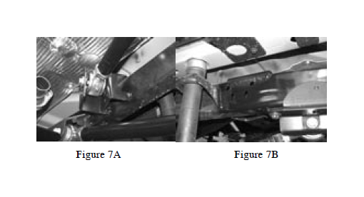
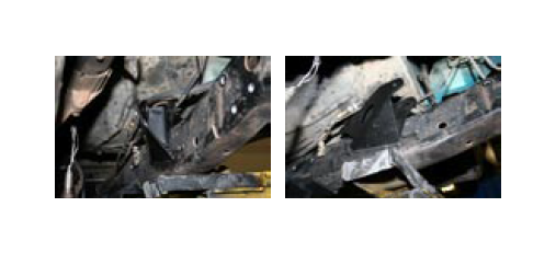
19. Install the rear upper control arm frame brackets near the rear body mount. The back of the frame bracket should be at least 1 inch in front of the body mount. (Figure 7A &B).
20. Install the rear upper and lower control arms. Final length adjustment must be done with the vehicle on the ground. This will be done at a later point. Install the upper control arm in the 2nd hole down from the top for neutral anti-squat. After completing installation of the kit you may want to try other settings to tune the rear suspension geometry to your vehicle and type of driving
21. Install the rear TeraFlex LCG springs. Set the aluminum bump stop spacer inside the TeraFlex spring as you put it up into place.
22. Once the spring is in place, install the bump stops using the supplied 3/8” x 2” self-tapping bolts to secure the bump stop to the spring pad.
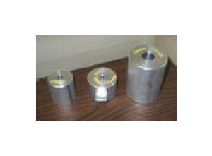
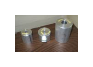
Note: The rear lower bumpstops are the same as are shown in the center of this photo. They measure 2 1/2” x 1 3/4” tall and have a spring retainer. The rear upper bumpstops are the same as are shown to the far left in this photo. They measure 2” x 2 1/4” tall.
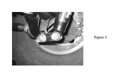
23. Install rear shock adapter brackets supplied with the LCG kit and install the rear shocks. (Figure 8).
24. Install the extended brake line hose and the extended sway bar links. Mount the extended brake line tee on top of the truss and reconnect the hard lines. Rear installation is complete.
25. Temporarily install the exhaust header pipe and the catalytic converter. Be very careful to avoid damage to the oxygen sensors and wiring as these are needed for proper operation of the fuel injection system. Final exhaust installation comes later.
Front Installation
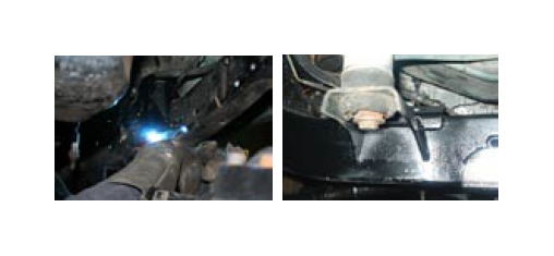
26. Install the new front upper PRO brackets on the inside of the frame rail with the locating ears going up over the frame and down on the outside to index with the body mount. Mark around the new bracket, then remove it and grind away the paint where the weld will be.
27. Weld the bracket to the frame and paint the weld area to prevent rust.
28. Install the upper control arms to the stock axle brackets and then to the new upper frame brackets after setting the length to approximately 24-1/2 inches.
29. Install the new lower control arms.
30. On the 4 inch Pro system install the front adjustable track bar in the stock brackets. On the 5 inch Pro system install the new track bar bracket. Hold it up in place and mark the frame where it will be welded around the edge. Clean the paint off the frame, and then bolt the tab on the new track bar bracket to the stock frame end track bar bracket. Use a large c-clamp to hold the bracket in place and tighten the bolt through the factory bracket, then weld the new bracket as shown in the next photos. Paint the weld areas.
31. Install the new track bar that comes with the 5 inch Pro system and move on to final assembly.
32. Using 5/16” drill bit, locate the center of the front, lower spring pad. The divot in the center works well as a guide. Drill a hole through the guide in the pad.
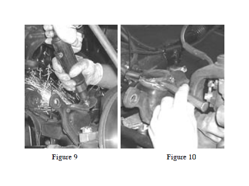
Note: Some 2003 and newer models have a plate welded on the center of the front axle spring pad. This metal plate must be drilled and tapped using a conventional thread tap 3/8-16. The self tapping bolt won’t cut threads in the thicker plate. The plate can be removed if you prefer by cutting the welds with a die grinder, then proceed as described in step above. (Figure 9 & 10).
33. Using the aluminum spacer as a guide, screw one of the self-tapping bolts (3/8” x 2”) into each hole to cut the threads and then remove the bolt and set aside.
34. Install the front TeraFlex LCG springs. Set the aluminum bump stop spacer inside the TeraFlex spring as you put it up into place.
35. Once the spring is in place, install the front bump stops. Use the supplied 3/8” x 2” self-tap bolts to secure the bump stop to the spring pad.
Note: The Front Lower bumpstops are the same as are shown at the far right of this photo. They measure 3” x 4” tall.
36. Install the front shocks and the extended brake line hoses and extended sway bar links if needed.
37. Bleed the brake system. Bleed the brakes starting with the passenger rear, driver rear, passenger front and finally driver front.
Final Assembly
38. Install the tires and lower the vehicle to the ground.
39. A temporary adjustment of the control arms can be made to locate the axles, then a four wheel alignment should be performed by a shop familiar with alignment procedures on lifted Jeep® vehicles.
40. The procedure for locating the axles is as follows:
a. Center the rear axle under the vehicle by adjusting the length of the upper triangulated control arms
b. Then make sure the axles are at right angles to the frame by adjusting one or the other lower control arm.
c. Finally set rear pinion angle and front caster angle by adjusting both lower arms an equal amount in or out as needed. d. Measure the wheelbase and be sure it is 94 inches before driving the vehicle to avoid bottoming out the front or rear drive shaft. Slight wheelbase adjustment is possible by adjusting all 4 front or rear arms. Then repeat steps a - c.
41. After final alignment, tighten all the jam nuts on all the control arms to ensure that arm lengths do not change.
42. Grease all control arms and other greasable components prior to operating the vehicle. Proper maintenance is essential to keep the joints free from dirt, water and other contaminants that will shorten the life and durability of the kit.
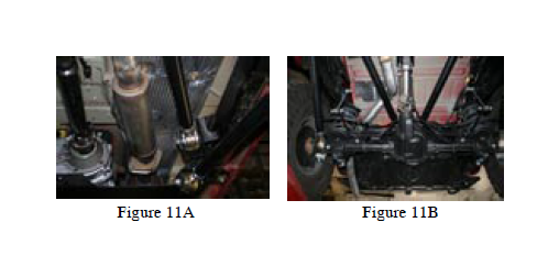
43. Have a competent exhaust shop weld in the exhaust patch, and install a suitable muffler and tailpipe that will clear the upper control arms through their full range of movement. See Figure 11A & 11B for suggested exhaust routing
After the first 100 miles of driving, re-torque lug nuts, recheck all LCG system fasteners, welds and jam nuts to make sure they are all still tight and secure.
LCG Instructions - Addendum - Rear Upper Shock Mount SARLCG January 18, 2005
The design of the SARLCG rear shock upper bracket allows the shock eyelet to extend through the frame allowing use of a longer rear shock.
Assemble the SARLCG bracket to the top shock eye using the special pan head bolt and thin nut provided with the kit.
Next install the shock as shown in the photo to the right with the new mount bracket extending up through the hole in the frame.
Note: This part of the frame is stamped out of two flat pieces of metal. Manufacturing tolerances may cause a slight interference where the two metal pieces overlap. If so, clear the opening in the frame with a file or die grinder to allow the shock to fit all the way up through the frame hole.
Mount the SARLCG to the frame using the original factory bolts at the top and assemble to the axle bracket with stock hardware or new hardware if provided in the shock kit.