FREE 1 to 3-Day Delivery on Orders $149+ Details

How to Install Teraflex 3 in. Elite LCG Long Arm Lift Kit w/ Shocks on your Wrangler
Important Notes
1. This installation is much easier if the Jeep is low on gas as you will be removing the fuel tank. If you have access to a lift, the best place to position the lift arms is directly under the body mounts to allow access for cutting, welding, axle droop, and placement of your new brackets. We recommend adding a jack stand to the rear of the vehicle for extra support. Place the vehicle in neutral to allow for easy driveline removal.
2. Disconnect the negative battery cable from the battery. Remove the tires.
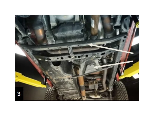
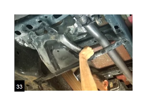
Remove the transfer case skid plate and exhaust skid plate/cross member. The exhaust skid plate will not be reused.
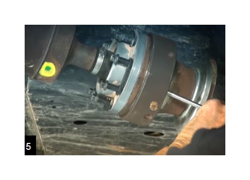
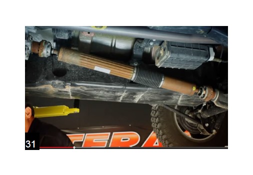
Skip steps 4-5 if you are not replacing the factory drivelines. Make a mark across the flanges at the axles and transfer case. Remove the 8 bolts at each CV end with a 5/16” socket. The front axle end is 4 bolts and a 15mm.
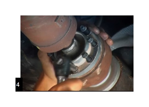
Through the two access holes in the rear flange, use a punch to free the driveline from the axle. Do not let the axle hang from the CV joint. The transfer case end will be easier to remove.
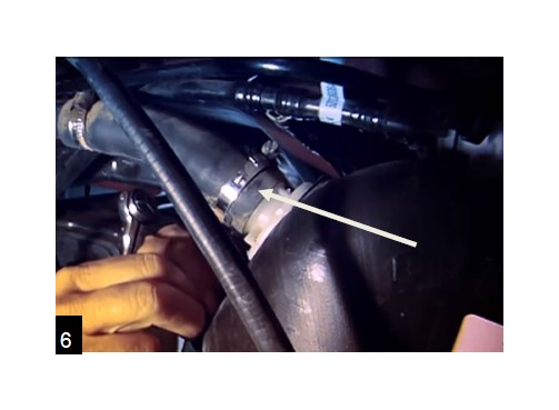
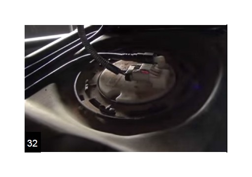
Removing the fuel tank is optional but highly recommended. Remove the filler neck with a 6mm.
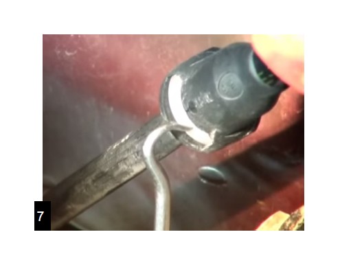
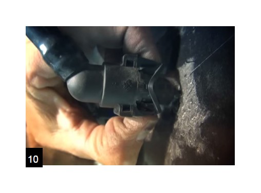
Use a screwdriver or equivalent to depress the white release to disconnect the vent line.
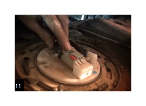
Disconnect the supply and return lines by squeezing the blue tabs. Caution! The supply line may still be under pressure. Have a rag ready to absorb any fuel leaks.
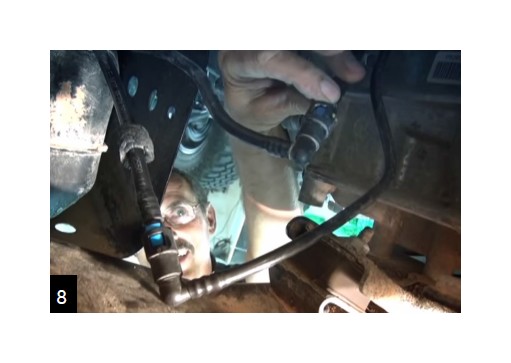
Be sure to cap/protect any open fuel lines. On most models the supply and return lines can be snapped together.
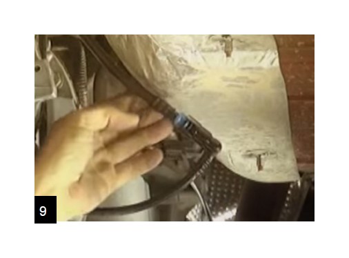
Disconnect the EVAP lines that run between the EVAP system and the fuel tank.
Remove the 8 bolts supporting the tank and slowly lower it. Beware of fuel/electrical lines that are still connected. Once you have access, remove the remaining electrical connections.
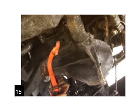
Lower the rear axle. Use a small strap around the rear pinion to help keep the axle in place, once the control arms are removed.
With the axle supported, remove all four rear control arms with a 21mm or an 18mm. Keep the hardware. Most nuts are captured nuts.
Support the front axle, un-bolt the bottom of the shocks with an 18mm (See 999207 Shocks/Front Removal).
Remove/un-clip all hoses and electrical wires that may bind. Lower the axle. Place a strap on the pinion.
Remove all four front control arms with a 21mm or an 18mm. Keep the hardware.
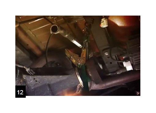
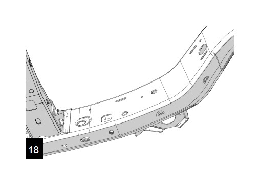
Un-clip all wire loom and fuel lines near where you will be cutting and welding. Tuck them above the frame or where they will not be damaged. With all control arms removed, begin cutting and removing the control arm brackets. Take extra care not to cut into the frame. Pay special attention to the direction of your flames and sparks as well as any hoses or wires that could be effected by the heat. Beware of any brake lines above the upper control arm mount on the drivers side as well. Avoid long, vertical welds on the frame; this may lead to cracking and frame failure.
After cutting is complete, grind down all remaining slag and metal to make a smooth surface for mounting the new brackets. We suggest using a flapper wheel on a 4” grinder.
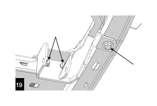
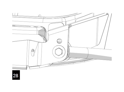
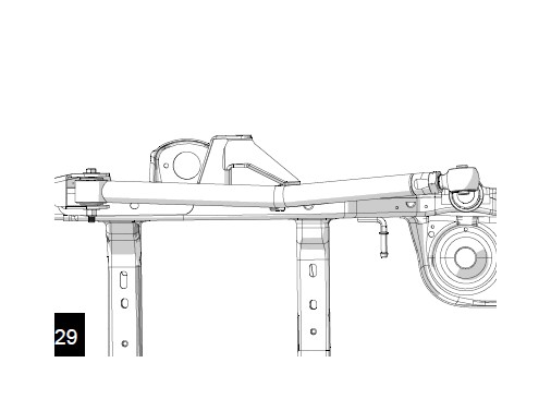
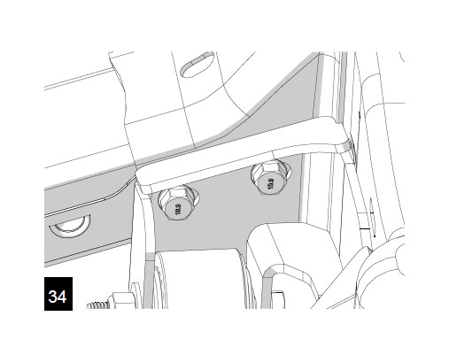
The front brackets index to a hole in the bottom of the frame and two bolts in the cross-member. Replace the cross-member bolts with longer, provided bolts. 2010-2011 See page 9-10 now.
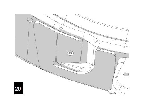
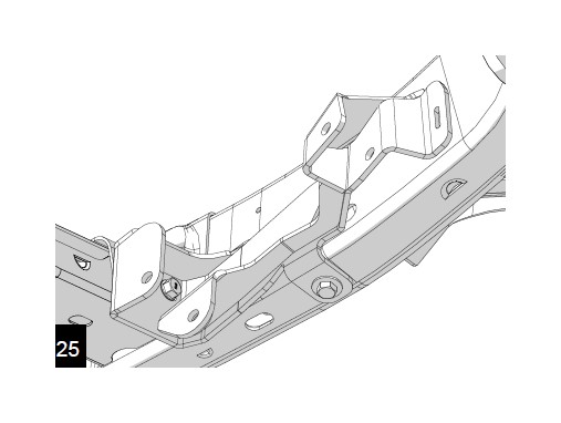
The rear gusset plate locates to a control arm hole in the frame. This will be welded in place before the rear bracket.
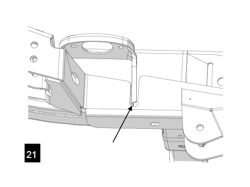
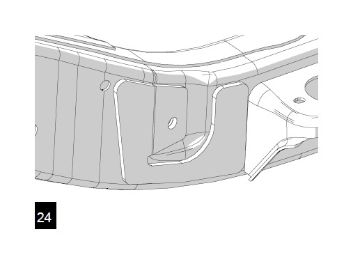
The rear brackets index around a body mount bracket. Cen-ter the slot in the bracket around the body mount.
Mark where the brackets and gussets will contact the frame. Clean off any paint within 1” of where welding will occur. A clean surface is key to a strong, lasting weld.
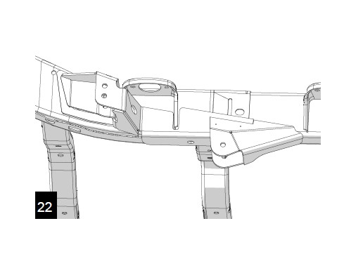
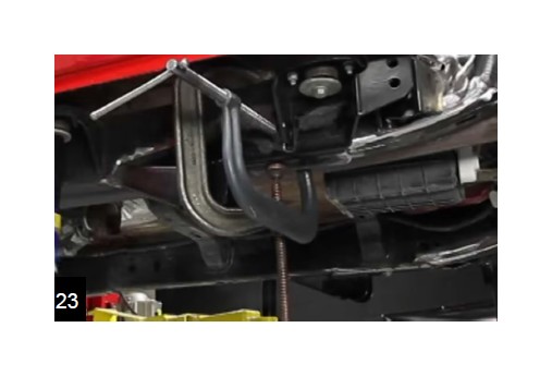
Use C-clamps to eliminate any gaps between the new brack-ets and the frame. Do several tack welds around the bracket to keep it from warping as you weld. Minimizing the bracket gap will make for a much better weld.
Weld the rear frame gussets on first. The rear brackets will weld to the new gussets. Weld on the rear brackets next.
25. Weld the front brackets. Take some time after welding to clean these sections and paint to prevent rust.
26. Lengthen the new arms. (Estimated lengths for a 4” lift,
center to center)
Front Uppers: 27 3/4”
Front Lowers:33 11/16”
Rear Uppers: 19 1/2”
Rear Lowers: 35 1/8”
All lifts must have a four wheel alignment after installation. This is essential to have a great driving Jeep.
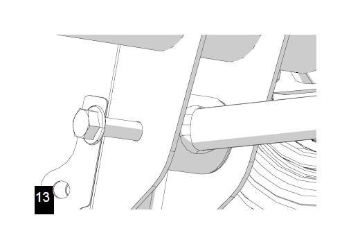
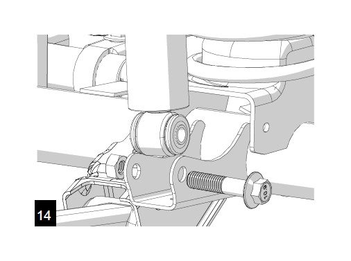
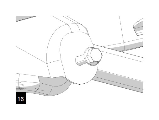
27. Install the new long arms with the flex joints at the axles. The new hardware will be used in the new frame brackets, Original hardware will be used at the axles. Do not completely tighten any joint or bushing until the Jeep is on the ground. This is important for bushing life, flex and ride quality.
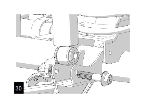
28. For most applications the rear upper arms will be mounted in the lower holes. Use the 9/16” x3.5” bolt and washers.
The rear lower arms are mounted with the bends up and in for maximum clearance. Use the 9/16” x 4.5” bolt and washers.
Raise the axle and reinstall the front shocks. (See 999207 Shocks/Front Installation)
Reinstall drivelines if applicable. Align the flange marks. At the transfer case; torque to 15 ft-lbs. Front axle flange; toque to 81 ft-lbs. Rear axle flange; torque to 15 ft-lbs.
Reinstall the fuel tank in the reverse order removed. Don’t forget any fuel lines, EVAP lines or electrical connections. Torque strap bolts to 30 ft-lbs.
Reinstall the transfer case skid plate. Torque bolts to 48 ft-lbs.
Torque the front bracket cross-member bolts to 90 ft-lbs.
Reinstall the tires, torque lug nuts to 95-110 ft-lbs. Remove supports and lower the vehicle to the ground. With the vehicle on the ground, torque front upper control arms to 75 ft-lbs, all other control arms to 125 ft-lbs.

2010-11 Exhaust Modification
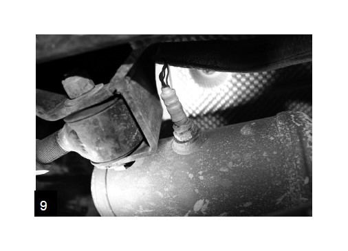
1. These years have a large, intrusive catalytic con-verter which will need to be cut out and moved. While orienting your catalytic converter, keep in mind that you may need access to your O2 sensor sooner or later. Place it in a location that will allow for removal of the sensor probe (1”).
2. Disconnect the sensor from the wiring harness by pinching the release and separating the plug.
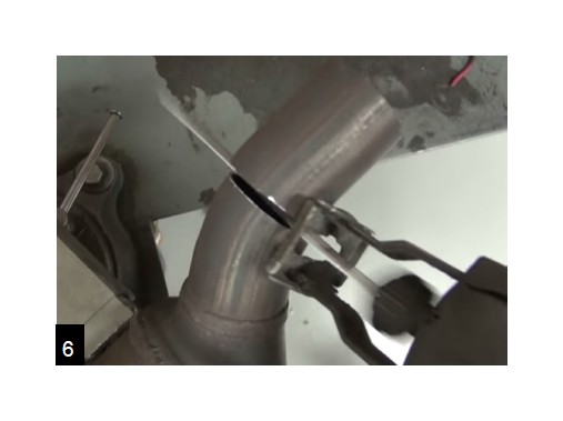
Use a reciprocating saw and cut as straight as possible in the straight pipe area just past the bend in front of the converter.
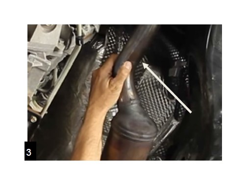
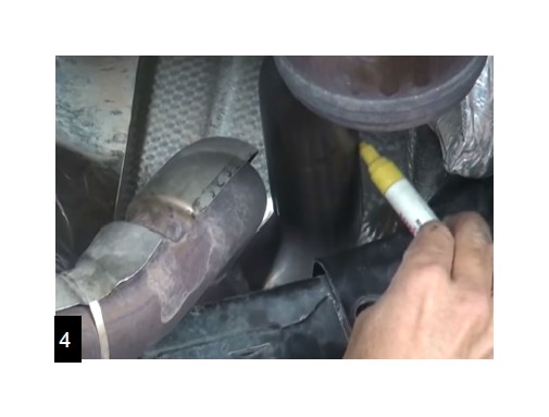
For the rear cut, give yourself plenty of room and cut in a straight section of pipe at least 2.5” from the bend into the converter.
5. Clean frame and front bracket of paint everywhere you will be welding. Clamp the bracket into place to close any gaps between the bracket and frame. Weld it on.
6. Cut about 2.5” of pipe off of the rear of the converter. Cut as square as possible, you will be reusing this section of pipe.
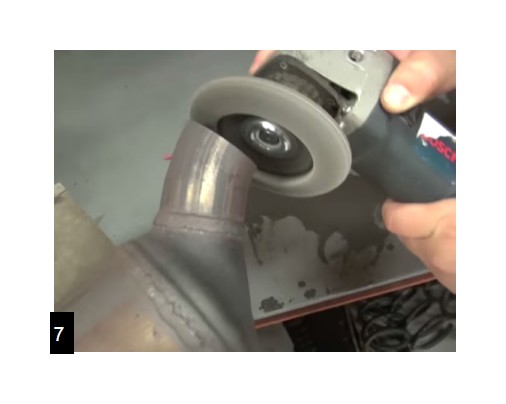
Use a grinder and clean up the cut ends of the exhaust pipe.
With the bracket welded in, hold the converter in place. The 2.5” section that was removed from the back will be moved to the front. You can either butt weld the pipes back together or use couplings.
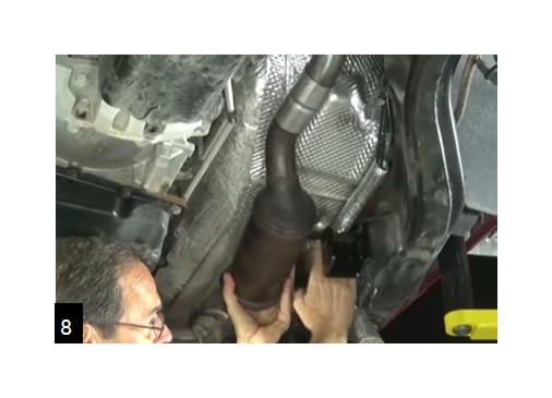
If the converter is properly oriented, the O2 sensor will be easy to remove and clear the new control arm bracket. With all clearances checked, weld in place.