FREE 1 to 3-Day Delivery on Orders $149+ Details

How to Install Teraflex 231 Extreme Short Shaft Kit on your 1987-2006 Wrangler

Shop Parts in this Guide
Installation:
Installing the 231ESS is basically the same as installing the original TeraLow 231SS. Read all of the instructions and look at the photos to familiarize yourself with the entire process before beginning installation.
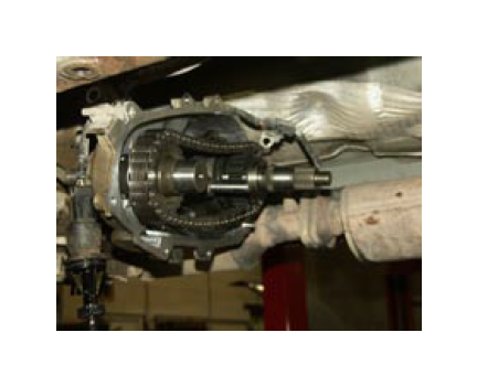
This rear shaft conversion can be completed with the transfer case in the vehicle although it might be easier to remove the transfer case and complete the installation on a workbench. These photos show the work being done with the case still in the vehicle.
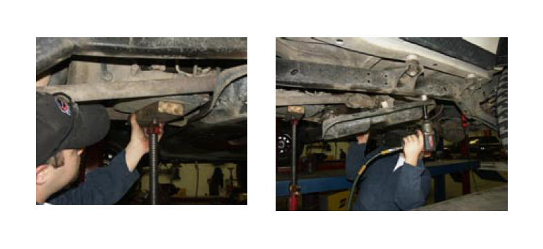
• Raise and securely support the vehicle.
• Drain the transfer case fluid
• Support the transmission and remove the factory cross member/skid plate.
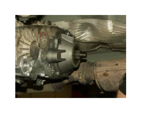
There are a couple of different styles of output slip yoke and housing on 231J transfer cases. The photo to the left is typical.
Remove the rear driveshaft completely. Then remove the front driveshaft at the transfer case yoke, and position it out of the way so you can get to the front output yoke to remove it. Remove
the nut and front output yoke.
Remove the dust shield or harmonic dampening ring from the factory output shaft and
remove the seal in the factory output housing.
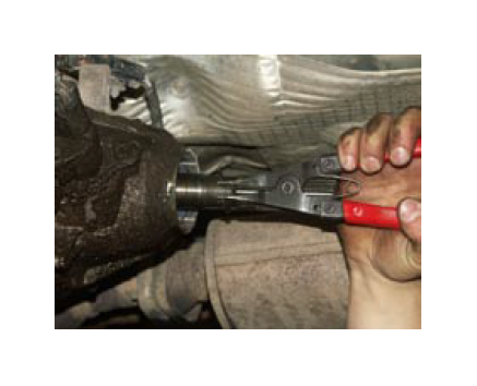
Using lock ring pliers remove the retaining ring that holds the output bearing in place on the factory output shaft.
On each end of the transfer case at the split line there are machined slots designed for using a screwdriver to pry the case halves apart. Make sure you have removed all the bolts, then use a flat blade screwdriver and gently separate the case halves. Make sure the output shaft stays in the front case half at this point. Be careful to not drop the oil pump as you lift off the rear case half.
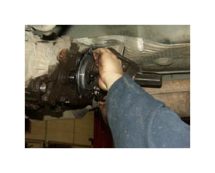
Then remove the speedometer drive gear assembly, unplug the 3 wire connector, remove the bolts that secure the output housing to the transfer case, and remove the output housing
Next remove the bolts that hold the case halves together. There are different style fasteners used here so pay attention to which bolts go in which holes for reassembly.
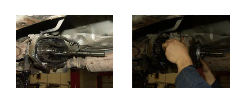
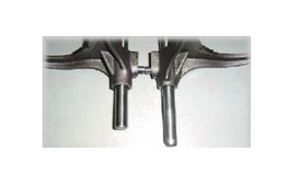
Next, carefully remove the output shaft, the front output gear and shaft, the drive chain and shift fork all together as an assembly and lay them on a clean workbench. Pay attention to the coil spring on the shift fork shaft. You will need to put it back on the shaft before assembling the back half of the transfer case.
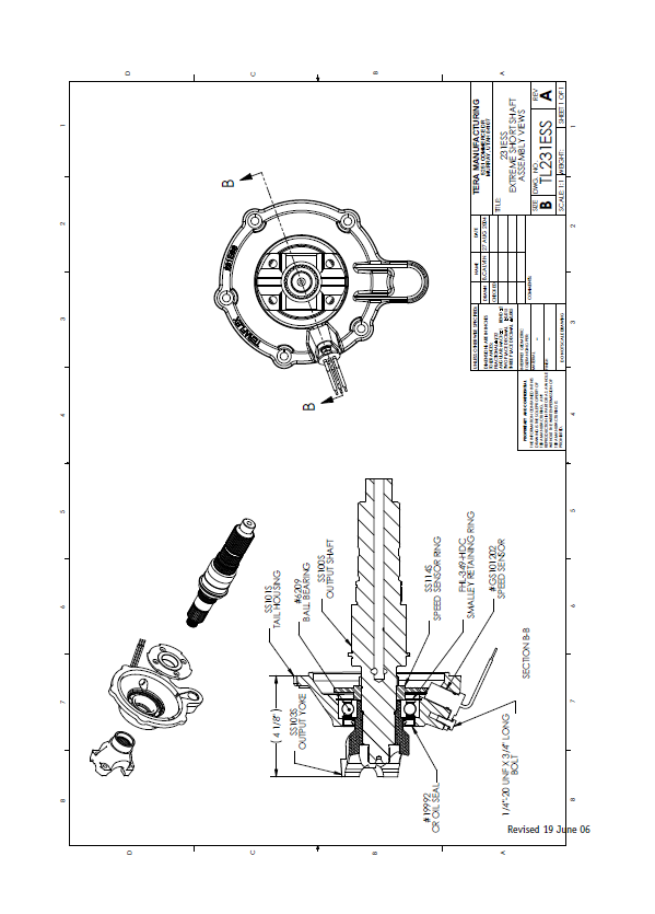
Note: Verify the length of your mode fork shift rod as shown. If your shift rod measures 10.2”, it will need to be cut down to a length of 9.380”. This is typical of 1988 and 1989 model YJ’s.
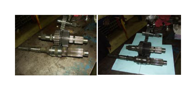
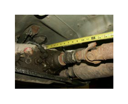
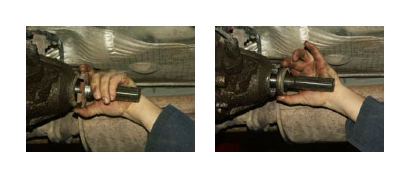
Notice the length difference between the stock output shaft and the new TeraLow
Extreme Short Shaft. It is a significant change.
Lift the factory rear output shaft out of the drive chain. Remove the lock ring that holds the drive sprocket and hub onto the factory output shaft and slide them off and then onto the new Extreme
Short Shaft.
Reinstall the lock ring, then place the new output shaft assembly back into the drive chain and prepare to reinstall the drive train back in the front case half by cleaning the case half mating surfaces
Carefully install the front and rear output shafts, drive chain and shift fork into the front case half. Reinstall the coil spring on the shift fork shaft.
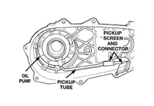
Be sure you didn’t get any grease or oil on the case half mating surfaces, then apply RTV silicone to the front case half. At this point make sure the magnet is placed securely in the slot of the front case half. Carefully install the oil pump on the outside of the rear case half and insert the pickup tube with o-ring.
Slide the speed sensor ring onto the Extreme Short Shaft with the taller shoulder facing the threaded end of the shaft.
Slide the rear case half over the rear output shaft and rotate the oil pump as needed to engage the splines. Slide the rear case half all the way onto the locating dowels and put in 1 bolt to hold everything in place.
Now check to make sure the oil pump pickup tube didn’t fall out of place. Install the remaining bolts that hold the case halves together and torque to 30 ft lbs.
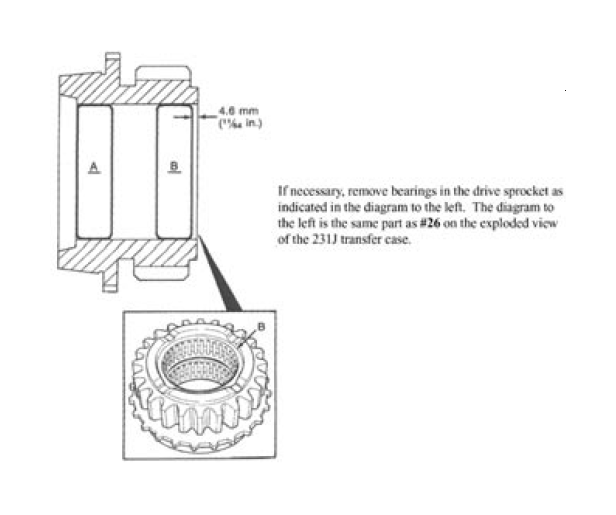
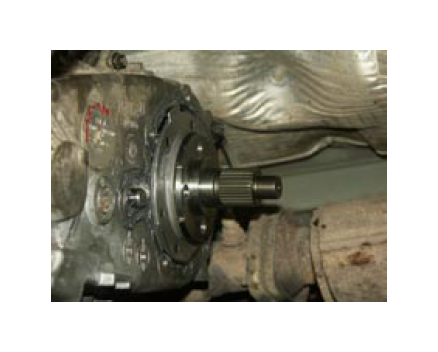
The bearing, snap ring and oil seal should be already installed in the new rear output housing when you receive it from your TeraFlex dealer. Clean the mating surface on the transfer case and apply RTV sealant. Install the new rear output housing and retaining bolts.
If the output housing won’t go up against the transfer case half then check to make sure the speed sensor ring is not installed backwards. You will notice a bevel on the outer diameter of the speed sensor ring that must match the slope of the casting and must line up square with the sensor so there is a minimum air gap between the sensor and the ring. NOTE: Refer to the section view drawing for proper installation of the tone ring.
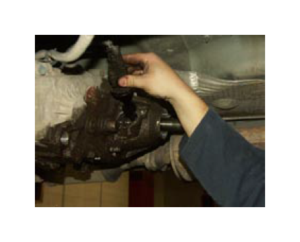
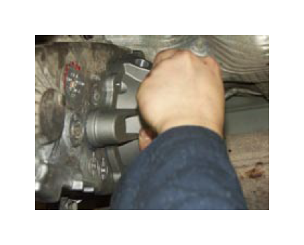
Next put some grease on the seal surface and install the output yoke with the new nut. NOTE: Install the four driveshaft bolts first. Tighten the yoke nut to 180 ft. lbs.
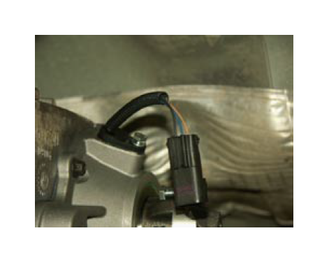
Install the speed sensor in the hole of the new tail housing. Use a little oil on the o-ring to ease installation. Install the retaining bolt and carefully tighten it to secure the sensor. No more than 7 ft. lbs. to avoid damaging the sensor.
Plug in the 3-wire connector into the factory harness connector.
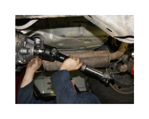
Install the rear driveshaft using the supplied 5/16-12 point bolts. We tried it with standard hex head bolts and learned that you cannot get a 1⁄2” wrench on the bolt head.
Reinstall the drain plug and fill the transfer case with the recommended
oil.
Reinstall the front driveshaft.
Reinstall the skid plate/cross member
assembly and lower the vehicle to the
ground.
Enjoy your new longer rear driveshaft.
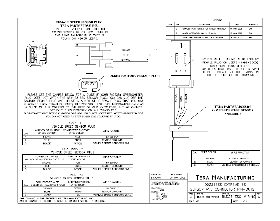
Wiring to work with older Jeeps such as 1997-98 TJ Wrangler:
In order to use the TeraFlex 231ESS in Wranglers and YJs built prior to 1999 it may be necessary to change the connector on the end of the factory chassis wiring harness. This will allow you to plug the speed sensor included with the TeraLow 231ESS directly into the vehicle wiring harness.
This wiring diagram shows the color code and location of the wires that will be changed.
Cut the plug off the vehicle side of the wiring harness right at the connector leaving you with 3 wires. TeraFlex can sell you the new female connector (TeraFlex Part Number 5202308) to go onto the factory wiring harness. Trim back the insulation and hook the wires up as shown in the diagram. The Violet/Orange wire is the 5V supply and hooks to the Brown wire on the new TeraFlex plug. The Brown/Yellow wire is the sensor ground and hooks to the Blue center wire on the new TeraFlex plug. The White/Orange wire carries the speed signal back to the computer and hooks to the black wire on the new TeraFlex plug. Solder all connections and cover with heat
shrink tubing and electrical tape to protect the wiring.