 FREE 1 to 3-Day Delivery on Orders $149+ Details

How to Install SuperLift Reflex Series Front Lower Control Arms for 2-4 in. Lift (07-18 Wrangler JK) on your Jeep Wrangler

Shop Parts in this Guide
- SuperLift Reflex Series Front Lower Control Arms for 2 to 4-Inch Lift (07-18 Jeep Wrangler JK)
- SuperLift Reflex Series Rear Lower Control Arms for 2 to 4-Inch Lift (07-18 Jeep Wrangler JK)
- SuperLift Reflex Series Front Upper Control Arms for 2 to 4-Inch Lift (07-18 Jeep Wrangler JK)
- SuperLift Reflex Series Rear Upper Control Arms for 2 to 4-Inch Lift (07-18 Jeep Wrangler JK)
INTRODUCTION
Installation requires a professional mechanic. The overall vehicle must be in excellent working condition; repair or replace all worn parts.
Read instructions several times before starting. Be sure you have all needed parts and know where they install. Read each step completely as you go.
NOTES:
•
Prior to beginning the installation, check all parts and hardware in the box with the parts list below. If you find a packaging error, contact Superlift® directly. Do not contact the dealer where the system was originally purchased. You will need the control number from each box when calling; this number is located at the bottom of the part number label and to the right of the bar code.
• A precision steering alignment, including the centering of the steering wheel, is required in order for the vehicle’s Electronic Stability Program to function properly. Using “all laser” alignment equipment is recommended.
• An arrow on diagrams indicates which direction is toward the front of the vehicle.
• A foot-pound torque reading is given in parenthesis ( ) after each appropriate fastener.
• Prior to drilling or cutting, check behind the surface being worked on for any wires, lines, or hoses that could be damaged. After drilling, file smooth any burrs and sharp edges.
• Paint or undercoat all exposed metal surfaces.
• Prior to attaching components, be sure all mating surfaces are free of grit, grease, excessive undercoating, etc.
• A factory service manual should be on hand for reference.
• Use the check-off box “” found at each step to help you keep your place. Two “” denotes that one check-off box is for the driver side and one is for the passenger side. Unless otherwise noted, always start with the driver side.
THESE INSTRUCTIONS DETAIL THE STEPS FOR ALL CONTROL ARMS. IF BOTH FRONT AND REAR CONTROL ARMS OR FRONT CONTROL ARMS ONLY WERE PURCHASED, PROCEED TO STEPS BELOW. IF REAR ONLY WERE PURCHASED, PROCEED TO STEPS IN “REAR PROCEDURES”.
FRONT PROCEDURES
NOTE: Save all factory components and hardware for reuse, unless noted.
1) PREPARE VEHICLE...
Place vehicle in neutral. Raise front of vehicle with a jack and secure a jack stand beneath each frame rail, behind the front / lower control arms. Ease the frame down onto the stands, place transmission in low gear or “park”, and chock rear tires. Remove front tires.
Position a jack so that it supports, but does not raise, the front axle.
IF THE LOWER CONTROL ARMS WERE THE ONLY FRONT CONTROL ARMS PURCHASED, PROCEED TO STEP 4.
2) REFLEX UPPER CONTROL ARM PREPARATION…
Reflex control arm length, measured from center of eye-to-center of eye, must measure 18-1/2”; verify that both control arms are set to this length. If adjustment is necessary, rotate the threaded end accordingly.
3) REFLEX UPPER CONTROL ARM INSTALLATION…
NOTE: Perform the steps in step 3 one side at a time, starting on the passenger side. Not all steps are required on driver side. Loosen, but do not remove, the single bolt that connects the passenger side motor mount to-frame.
Remove the three nuts that secure the transmission isolator-to-transmission crossmember.
Position a jack with a block of wood under the oil pan. Raise the jack so that the engine will tilt / rotate towards the driver side of vehicle. This will allow clearance needed to remove the control arm bolt at the frame on the passenger side without removing the exhaust.
Remove the bolt from the factory control arm’s axle and frame ends then remove control arm.
Attach the bushing end of the Reflex control arm-to-frame using the factory bolt and tab nut. Do not tighten yet.
Attach the bracket end of the Reflex control arm-to-axle using the factory hardware. Do not tighten yet.
Lower the jack supporting the oil pan.
Tighten the motor mount hardware on the passenger side (80).
Reinstall the three nuts that secure the transmission isolator-to-transmission crossmember (40).
Repeat appropriate steps for driver side control arm installation. On this side it is not necessary to loosen motor and transmission mounts, nor elevate the engine; simply remove the factory control arm then install the Reflex unit. Again, do not tighten any hardware at this time.
IF THE UPPER CONTROL ARMS WERE THE ONLY FRONT CONTROL ARMS PURCHASED, PROCEED TO STEP 5.
4) REFLEX LOWER CONTROL ARM INSTALLATION…
NOTE: Perform the steps in step 4 one side at a time Remove the factory front lower control arm.
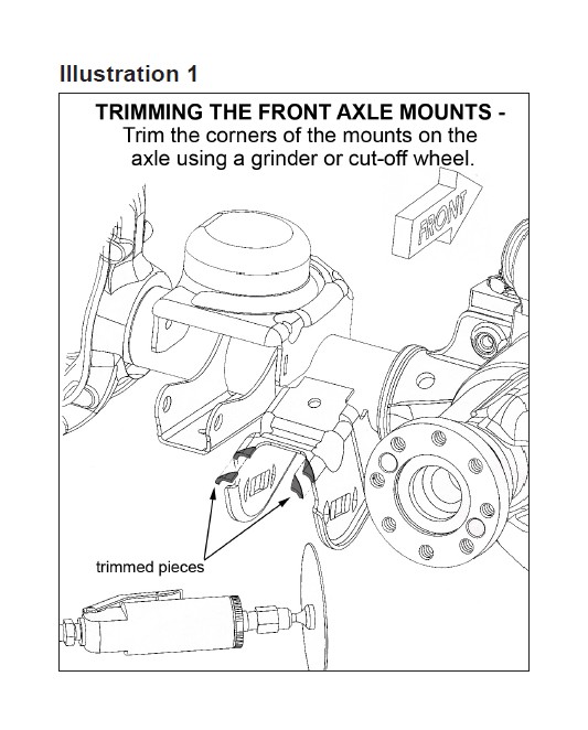
[Illustration 1] Using a grinder, clearance the lower control arm mounts at the axle, as shown. Not much trimming is required; simply remove the mount’s top radius.
When installing the Reflex control arms they do need to be orientated correctly. The bend in the arm should point up when installed. Attach the Reflex control arm-to-frame using the factory hardware; install the bolt from the outside. Do not tighten the control arm bolt yet.
One side at a time, remove the rear knock-outs that change the opening from a square hole to a slotted hole. A special tool is available for this, or use a die grinder with a small cutting wheel.
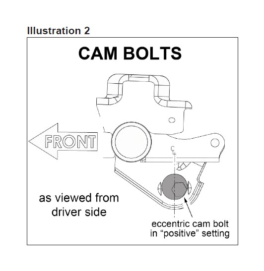
[Illustration 2] Reconnect lower control arms to the axle using the supplied cam bolts (#77-5704A), installed from the outside. Rotate the cams to their “most positive” setting, so that the front axle is shifted as far forward as possible (the bolt head will be in its most rearward position). Snug-up the bolts; do not fully tighten at this time.
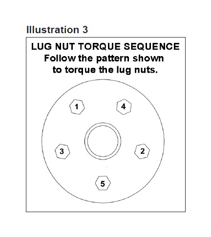
5) TIRES / WHEELS... [Illustration 3]
Tighten the lug nuts (115) in the sequence shown.
WARNING: When the tires / wheels are installed, always check for and remove any corrosion, dirt, or foreign material on the wheel mounting surface, or anything that contacts the wheel mounting surface (hub, rotor, etc.). Installing wheels without the proper metal-to-metal contact at the wheel mounting surfaces can cause the lug nuts to loosen and the wheel to come off while the vehicle is in motion.
WARNING: Retighten lug nuts at 500 miles after any wheel change, or anytime the lug nuts are loosened. Failure to do so could cause wheels to come off while vehicle is in motion.
6) INITIAL CLEARANCE CHECK, FRONT...
With the vehicle still on jack stands, and the suspension “hanging” at full extension travel, cycle steering lock-to-lock and check all components for proper operation and clearances. Pay special attention to the clearance between the tires / wheels and brake hoses, wiring, driveshaft-to-crossmember, etc.
Lower vehicle to the floor. Final tightening and adjustments to the front suspension will take place once rear lift is completed.
IF NO REAR CONTROL ARMS WERE PURCHASED, PROCEED TO “FINAL PROCEDURES”.
REAR PROCEDURES
7) PREPARE VEHICLE...
Place vehicle in neutral. Raise rear of vehicle with a jack and secure a jack stand beneath each frame rail, just ahead of the rear / lower control arms. Ease the frame down onto the stands, place transmission in low gear or “park”, and chock front tires. Remove rear tires.
Position a jack so that it supports, but does not raise, the rear axle.
IF THE LOWER CONTROL ARMS WERE THE ONLY REAR CONTROL ARMS PURCHASED, PROCEED TO STEP 9.
8) REFLEX UPPER CONTROL ARM INSTALLATION… NOTE: Perform the steps in step 8 one side at a time.
Remove the bolt from the factory control arm’s axle and frame ends then remove control arm. Install the Reflex arm with the bend pointing up and the short end of the arm to the frame; secure using the factory hardware. Do not tighten at this time.
IF THE UPPER CONTROL ARMS WERE THE ONLY REAR CONTROL ARMS PURCHASED, PROCEED TO STEP 11.
9) REFLEX LOWER CONTROL ARM PREPARATION…
Reflex control arm length, measured from center of eye-to-center of eye, must measure 19-3/4”; verify that both control arms are set to this length. If adjustment is necessary, rotate the threaded end accordingly.
10) REFLEX LOWER CONTROL ARM INSTALLATION… NOTE: Perform the steps in step 10 one side at a time.
Remove the bolt from the factory control arm’s axle and frame ends then remove control arm.
Install the Reflex arm with the adjustable end at the frame mount using the factory hardware. Do not tighten at this time.
11) TIRES / WHEELS…
Tighten the lug nuts (115) in the sequence shown in illustration 3.
WARNING: When the tires / wheels are installed, always check for and remove any corrosion, dirt, or foreign material on the wheel mounting surface, or anything that contacts the wheel mounting surface (hub, rotor, etc.). Installing wheels without the proper metal-to-metal contact at the wheel mounting surfaces can cause the lug nuts to loosen and the wheel to come off while the vehicle is in motion.
WARNING: Retighten lug nuts at 500 miles after any wheel change, or anytime the lug nuts are loosened. Failure to do so could cause wheels to come off while vehicle is in motion.
FINAL PROCEDURES
12) INITIAL CLEARANCE CHECK, REAR…
With the vehicle still on jack stands, and the suspension “hanging” at full extension travel, check all components for proper operation and clearances. Pay special attention to clearance between the tires / wheels and brake hoses, driveshaft, etc.
13) HARDWARE TIGHTENING SEQUENCE…
Remove jack stands and lower vehicle to the floor. The suspension is now supporting vehicle weight.
All rear control arms-to-frame and axle (125).
Front / lower control arms-to-frame and axle (125).
NOTE: Be sure that eccentric cam bolts are positioned as per installation step.
Front / upper control arms-to-frame and axle (75).
14) FINAL CLEARANCE and TORQUE CHECK...
Cycle steering lock-to-lock and inspect the tires / wheels, and the steering, suspension, and brake systems for proper operation, tightness and adequate clearance.
15) ALIGNMENT...
Realign vehicle to factory specifications. A precise alignment, including the centering of the steering wheel, is required in order for the vehicle’s Electronic Stability Program to function properly. A laser alignment is recommended.
16) SUPERLIFT WARNING DECAL…
The WARNING TO DRIVER decal installs on the inside of the vehicle within the driver’s view. Prior to installation, pre-clean the surface with the supplied alcohol cleaning pad.
17) SUPERLIFT BADGES...
This kit is packaged with a Superlift badge. Prior to installation, use the supplied alcohol pad to eliminate all soap and or other non-adhering residues that may impair adhesion, thoroughly clean the entire area of placement.
Remove the adhesive back and place small badge in the desired location. The adhesive on our badges is pressure sensitive and must be applied using pressure on all areas of the graphic. Like any PSA (pressure sensitive adhesive), it can take up to 72 hours for the adhesive to fully cure. Once the badge is in place do not peel it up, this will diminish the adhesive properties and could result in damaging the badge itself
To keep your Superlift badge in “like new” appearance keep the badge free/clear of solvents and chemicals that could cause the adhesive to dry or dissolve. This includes gasoline, diesel fuel, paint thinner, and alcohol. Soap and water is all that is needed for cleaning. Degreasers can be used sparingly and hand wiped/applied if needed, although not suggested.
