
How to Install SuperLift Adjustable Front Track Bar for 2-6 in. Lift (07-18 Wrangler JK) on your Jeep Wrangler
INTRODUCTION
Installation requires a professional mechanic. Prior to beginning, inspect the vehicles steering, driveline, and brake systems, paying close attention to the suspension link arms and bushings, anti-sway bars and bushings, tie rod ends, pitman arm, ball joints and wheel bearings. Also check the steering sector-to-frame and all suspension-to-frame attaching points for stress cracks. The overall vehicle must be in excellent working condition; repair or replace all worn parts.
Read instructions several times before starting. Be sure you have all needed parts and know where they install. Read each step completely as you go.
NOTES:
• Prior to beginning the installation, check all parts and hardware in the box with the parts list below. If you find a packaging error, contact Superlift directly. Do not contact the dealer where the system was originally purchased. You will need the control number from each box when calling; this number is located at the bottom of the part number label and to the right of the bar code.
• A foot-pound torque reading is given in parenthesis ( ) after each appropriate fastener.
• Do not fabricate any components to gain additional suspension height.
• A factory service manual should be on hand for reference.
• Use the check-off box “” found at each step to help you keep your place. Two “” denotes that one check-off box is for the driver side and one is for the passenger side. Unless otherwise noted, always start with the driver side.
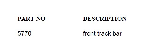
PARTS LIST … The part number is stamped into each part or printed on an adhesive label. Identify each part and place the appropriate mounting hardware with it.

INSTALLATION PROCEDURE
1) PREPARE VEHICLE...
Position the vehicle on a level surface with the front tires pointing straight ahead. Put the vehicle in park or First gear, set the emergency brake, and chock the rear wheels to prevent any possibility of movement. The vehicle should remain on the ground with the suspension “loaded” at normal operating weight to reflect the true ride height.
2) TRACK BAR REMOVAL…
Prior to removing the stock track bar, inspect the attaching points for movement while
moving the steering wheel left and right. The axle and frame mounting holes tend to
elongate. If any of these conditions exist, repair the attachment points before proceeding. Any looseness will create tire / wheel shimmy.
Remove the factory track bar from the vehicle and set aside. Save hardware for reuse.
3) TRACK BAR…
Insert the “adjustable” end of the track bar in mount on the axle. Secure using the factory bolt. Do not tighten at this time.
Position the upper end of the bar in the track bar mount on the frame and secure it using the factory bolt. Do not tighten at this time.
4) FRONT TRACK BAR ADJUSTMENT…
Verify that the tires are pointed straight ahead. Position a plumb bob or similar tool against the inside edge of the frame. Measure the distance between the line of the plumb bob and the inside edge of the wheel. Record this measurement, then repeat the procedure on the other side.
Compare the two measurements recorded in the previous step; the goal is to make them equal. If the driver side measurement is greater than the passenger side, the track bar needs to be lengthened. If the passenger side measurement is greater than the driver side, the track bar needs to be shortened. In most cases, the track bar on a lifted vehicle needs to be longer than stock.
Remove the lower end of the track bar from the vehicle and make the appropriate
adjustments. Tighten the jam nut firmly, then reattach the bar to the axle and torque (130).
Wiggle the front tires back and forth several times to fully seat the track bar. Repeat the measuring procedure to verify the adjustments made were correct.
NOTE: The maximum amount of adjustment is no more than 1-1/8” of exposed threads as measured from the end of the track bar.
5) FINAL CLEARANCE and TORQUE CHECK...
With vehicle on floor, cycle steering lock-to-lock and inspect the tires / wheels, and the steering, suspension, and brake systems for proper operation, tightness, and adequate clearance.

