 FREE 1 to 3-Day Delivery on Orders $149+ Details

How to Install SuperLift 3.5 in. Suspension Lift Kit w/ Superide Shocks (87-95 Wrangler YJ) on your Jeep Wrangler

Shop Parts in this Guide
INTRODUCTION
Installation requires a professional mechanic. Prior to beginning, inspect the vehicles steering, driveline, and brake systems, paying close attention to the suspension link arms and bushings, anti-sway bars and bushings, tie rod ends, pitman arm, ball joints and wheel bearings. Also check the steering sector-to-frame and all suspension-to-frame attaching points for stress cracks. The overall vehicle must be in excellent working condition; repair or replace all worn parts.
Read instructions several times before starting. Be sure you have all needed parts and know where they install. Read each step completely as you go.
NOTES:
• Front / rear springs and shock absorbers (purchased separately) are also required.
• On diagrams, an arrow symbol indicates which direction is towards 'front of vehicle".
• A foot pound torque reading ( ) is given after each appropriate fastener.
• Do not add or fabricate any components to gain additional suspension height.
• After drilling, file smooth any burrs or sharp edges or stress cracks may develop.
• Paint or undercoat all exposed metal surfaces.
• Prior to attaching components, be sure mating surfaces are free of grit, grease, undercoating, etc.
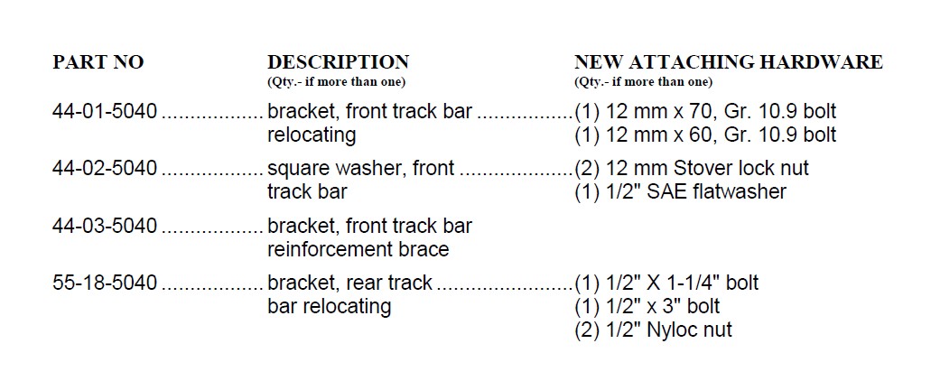
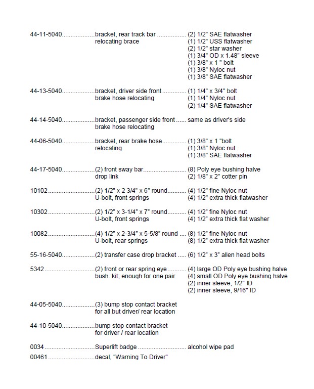
PARTS LIST … The part number is stamped into each part or printed on an adhesive label. Identify each part and place the appropriate mounting hardware with it.
FRONT PROCEDURE
1) PREPARE VEHICLE...
Prior to placing the front of vehicle on jack stands (performed in next step), remove the stock sway bar drop links. The links (one per side) connect the anti-sway bar body to the U-bolt plates.
To dislodge the links' upper ends, which are tapered studs, use hammer strikes to the bar body near the link-to-body attaching point. Do not strike the stud.
With the transmission in neutral, raise front of vehicle with a pneumatic bumper jack or two floor jacks positioned on either side of the front axle. Place jack stands under the frame rails directly behind the front springs' rear hangers. Lower the frame onto the stands. Put vehicle in gear or "park", set emergency brake and chock rear tires. Remove front tires, wheels, and shocks
2) TRACK BAR / BRAKE HOSES…
Detach the bottom end of track bar from its axle mounting bracket then tie bar up and out of the way.
The upper end of the front brake hoses attach to the top of each frame rail with one Torx bolt located directly behind the shock towers. Remove the bolts; access is gained through the engine department.
3) FRONT SPRINGS…
Remove the four front spring-to-axle U-bolts. NOTE: The remainder of spring removal and installation is performed one side at a time:
On the driver's side, position a floor jack beneath the axle tube, just inboard of the leaf spring. Raise the jack until the axle just separates from the spring. Now, detach the spring from its hangers.
Prior to installation, thoroughly lubricate the new spring eye bushings and sleeves with a water resistant, Lithium based grease. Loosely attach the spring to its hangers; snug-up but do not completely tighten the mounting bolts yet. Note that the large diameter eye takes the larger diameter sleeve and installs at the stationary mount, opposite the pivoting shackle end.
NOTE: If the vehicle is equipped with factory spring shims, reuse these shims with the supplied springs.
Repeat the spring removal and installation procedure on the passenger's side.
4) U-BOLTS…
Make sure the the spring perches and the the springs are clean and free of any debris.
Position the front axle onto the springs being sure the tie bolt heads align and seat into the spring perch holes.
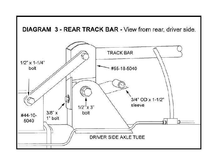
While installing the front U-bolts, locate one #44-05-5040 bump stop bracket onto the top of the axle tubes. Diagram 3 shows how the bump stops are captured by the U-bolts. Note that only the driver's side / rear bump stop is held in place by two U-bolts. The other three bump stops are captured by one single U-bolt. When tightening the U-bolts (1 00), keep the bracket positioned so that when the suspension compresses, the stock bump stop will contact the top of the bracket flush, not at an angle. Use an "X' tightening sequence when torquing the U-bolts.
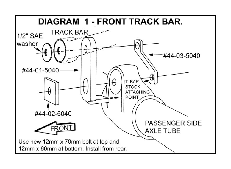
[DIAGRAM 1] The front track bar relocating bracket and hardware installs as per Diagram 1. Before tightening the bracket-to-axle bolt, be sure that bracket position is perfectly vertical, not leaning to either side. The bar-to-bracket bolt is not installed until a later step, when vehicle weight is on the suspension.
Install front shock absorbers. Tighten upper stem type mounts only until bushings swell slightly then torque lower mounts (45).
5) BRAKE HOSES…
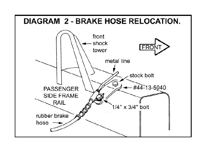
If Superlift extended length brake hoses are being used, install now as per separate instructions. If the stock hoses are retained, install the Superlift relocating brackets as per Diagram 2. Note that there is a driver (#44-13-5040) and a passenger side (#44-14- 5040) bracket.
6) TRACK BAR / FRONT FASTENER TIGHTENING …
Install tires / wheels (80-110), remove jack stands and lower vehicle to floor.
Tighten the front springs' shackle (95) and stationary (105) ends.
Attach the bottom end of the track bar to the Superlift bracket (99) using the hardware shown in Diagram 1. It may be necessary to turn the steering wheel slightly either left or right to achieve bolt-to-bracket alignment.
7) SWAY BAR LINKS…
Lubricate the sway bar drop link eye Poly bushings, then insert them into the new links' eyes. Remove the tapered studs, found at the top of the stock links, and insert into the new links. Tighten the top and bottom link ends (45) then insert new cotter pins.
REAR PROCEDURE
8) PREPARE VEHICLE…
Raise rear of vehicle and place jack stands beneath frame rails, directly in front of rear springs' front hangers. Lower the frame onto the stands, then chock front tires. Remove rear tires / wheels and shocks.
9) BRAKE HOSE…
If Superlift extended length brake hose is being used, install now as per separate instructions. If not, remove the retainer clip that attaches the stock rubber brake hose to its upper mounting bracket. This is where the rubber hose ends and the metal line starts. Insert the new "Z" shaped bracket (#44-06-5040) in between the stock mounting bracket and the hose end. The 3/8" hardware is used at the bracket-to-bracket end. Position the hose / line through the slot and into the hole on the "Z" bracket's opposite end, then reinstall clip.
10) TRACK BAR REMOVAL…
Unbolt the bottom end of the track bar from the driver side of the rear axle and tie it up and out of the way.
11) SPRING REMOVAL / INSTALLATION...
Remove rear U-bolts.
Lubricate and install the spring eye bushings and then the springs using the same procedures used at front of vehicle. Note that the thick end of the spring degree shims (already attached to the springs) should point towards front of vehicle. Again, do not fully tighten spring eye bolts yet. This is performed in a later step.
12) BUMP STOP BRACKETS…
Make sure the spring perches and the springs are clean and free of any debris.
Position the front axle onto the springs, being sure the tie bolt heads align and seat into the spring perch holes.
As with the front end, the compression travel bump stops are held in place on top of the axle tubes by the U-bolts. On the passenger side, one single U-bolt captures #44-05-5040 bump stop. For the driver side, bump stop #44-10-5040 has "lips" on both sides and is captured by both U-bolts. Torque new rear U-bolts, flatwashers and Nyloc nuts (90) using an "X" tightening sequence.
13) TRACK BAR BRACKET #44- 04-5040…
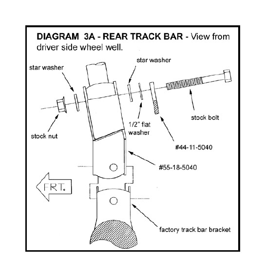
[DIAGRAM 3 and 3a] Position bracket #55-18-5040, with its slotted hole to the top, onto the stock track bar-to-axle mount, as shown in the diagrams.
First, loosely install the 3/8" hardware, then the spacer sleeve and 1/2" lower bolt. Now tighten the hardware in the same order. The bar and brace are installed in a later step.
14) SHOCKS…
Install shocks, torquing upper and lower mounts (45).
NOTE: Some models may exhibit light contact between the shock body and axle tube. Because the contact is light, it does not affect the performance of the suspension or the shock. If this is unacceptable, your options are: (A) use a smaller body shock (B) relocate shock brackets.
15) TIRES / WHEELS...
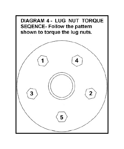
[DIAGRAM 4] Tighten the lug nuts (80-110) in the sequence shown.
WARNING: When the tires / wheels are installed, always check for and remove any corrosion, dirt, or foreign material on the wheel mounting surface, or anything that contacts the wheel mounting surface (hub, rotor, etc.). Installing wheels without the proper metal-to-metal contact at the wheel mounting surfaces can cause the lug nuts to loosen and the wheel to come off while the vehicle is in motion.
WARNING: Retighten lug nuts at 500 miles after any wheel change, or anytime the lug nuts are loosened. Failure to do so could cause wheels to come off while vehicle is in motion.
Lower vehicle to the floor.
16) REAR FASTENER TIGHTENING SEQUENCE…
Manually bounce the front and rear suspension several times to “seat” the springs.
Tighten the rear springs’ shackle (95) and stationary (105) ends.
17) REAR TRACK BAR BRACE…
Attach the bottom end of the track bar to the Superlift bracket with brace # 44-11-5040 and additional hardware positioned onto the stock bolt as shown in Diagram 3. The bolt locates itself in the slot and the star washers help secure it there. Snug-up, do not torque, the bar-to-bracket bolt, then position the lower end of brace onto the bump stop bracket.
With the brace properly located, drill a 1/2" hole into the bump stop through the existing hole in the brace. Install furnished 1/2" hardware (57) at the new hole and torque the stock upper bolt (99).
18) LOWERING THE TRANSFER CASE…
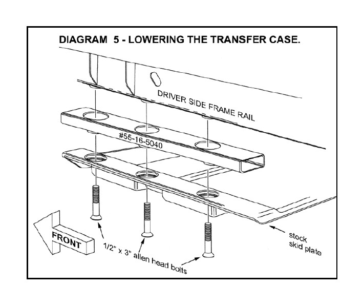
[Diagram 5] There are two or three bolts, towards the skid plate's center, that tie the transfer case to the plate. Loosen, but do not remove these bolts.
Position a floor jack beneath the skid plate and slightly load the jack. On each side, remove the 3 skid plate-to-frame bolts and lower the assembly enough to insert the #55-16-5040 drop brackets.
Note that the spacers' concave surface mates against the plate. Install the supplied 1/2” x 3” allen-head bolts. Now tighten the skid plate (30) and transfer case mount bolts (33).
NOTE: Lowering the skid plate assembly can affect transmission shifting functions. Refer to the appropriate MANUAL or AUTOMATIC instructions:
MANUAL TRANSMISSION - When shifting into Reverse, check for clearance between the stick and floor pan. If there is interference, trim away the pan as required. Normally, no more that 1/4" of material must be removed. Also, it may be necessary to move the center console rearward slightly. If so, the stock self-tapping screws can be reused.
AUTOMATIC TRANSMISSION - The engine should crank only if the vehicle is in Park or Neutral. The transmission's shift linkage must be readjusted if the vehicle cranks in one but not both positions, or if it will crank in any other position. If adjustment is required, it must be performed by a qualified Jeep technician.
19) FINAL PROCEDURES AND TORQUE CHECK…
With the front tires pointing perfectly straight ahead, the steering wheel cross bars will be misaligned. To center the steering wheel, loosen the two clamp bolts on the drag link adjustment sleeve and rotate the sleeve until the desired steering wheel position is achieved. Then tighten the clamp bolts (33).
Cycle steering lock-to-lock and inspect steering, suspension and driveline systems for proper operation, tightness, and adequate clearance. If brake hose fittings were touched, recheck them for leaks. Be sure all hoses / wiring are of adequate length. Now, raise vehicle again and reposition jack stands. With the suspension unloaded and "hanging", repeat the above inspection procedures.
NOTE: With some vehicles, engine torque, while under heavy loads, can cause the transfer case to make contact with the rear lip of the skid plate. If this occurs, space the rear of the plate down further by adding one or two washers per side to the top of the rear spacers.
20) Activate four wheel drive system and check front hubs for engagement
21) HEADLIGHTS...
Readjust headlights to proper setting.
22) SUPERLIFT NAME BADGE AND WARNING DECAL... The system includes one 2” x 5” name badge (#0034). Additional and / or larger badges are available from Superlift or a Superlift dealer. We suggest putting the badges on the front fenders, tailgate, or rear window. The badge mounts by means of factory applied, double-backed tape. Follow these instructions to ensure that badge sticks properly:
Clean designated area with warm, soapy water. Rinse and wipe dry with a soft, lint free towel.
Thoroughly prep the area with the furnished alcohol wipe pad and wipe dry with a soft, lint free towel. Do not touch the surface again with your hands; they transfer body oils.
Remove mounting tape backing, line up badge, and press in place. Do not touch mounting tape or allow tape to get dirty.
Press firmly on the badge face and hold a few seconds to seat mounting tape. A superior adhesive bond forms over time. We recommend allowing 24 hours of cure time before washing and waxing. The emblem itself can be cleaned with any glass cleaner.
Install the WARNING TO DRIVER decal on the inside of the windshield, or on the dash, within driver’s view. Refer to the “NOTICE TO DEALER AND VEHICLE OWNER” section below.
23) ALIGNMENT...
Front end alignment has not been affected by this system, but we suggest that alignment be checked to improve tire wear characteristics and driveability.
