FREE 1 to 3-Day Delivery on Orders $149+ Details

How to Install a Sprintex Non-Intercooled Superchager System with Hypertech Tuner on your Wrangler
Tools Required
- Metric Wrenches and Socket Sets
- Metric Allen keys
- Flat and Philips Screwdrivers
- Pliers and Side Cutters
- Cable Ties
- Electrical Tape
- Loctite 577 thread locker
- Loctite 406
- Cobra clamp pliers
- Solder and Soldering Gun
- Rubber grease or Silicone spray
- ½” Breaker bar

Sprintex recommends performing the following vehicle checks prior to installing the supercharger.
1. Check that the factory fuel system is operating correctly.
2. Inspect the factory exhaust catalyst for blocks or damage
3. Ensure that the vehicles ignition system is working correctly.
4. Install new standard spark plugs and set gap.
5. Replace the fuel filter if the vehicle has travelled more than 15,000 Km or 9000 miles.
6. It is recommended to run at least one full tank of premium unleaded fuel through the vehicle prior to installing the supercharger system to prevent any possible damage that may occur due to running the supercharged engine on lower octane fuel. (Refer details on the next page)
CHANGES TO FACTORY SPECIFICATIONS
FUEL: MINIMUM 95 RON (91 Octane USA) PREMIUM UNLEADED GASOLINE/FUEL TO BE USED AT ALL TIMES. NEVER ALLOW THE ENGINE TO KNOCK OR DETONATE AS SERIOUS ENGINE DAMAGE MAY OCCUR.
REQUIRED SERVICE: (SEE MAINTENANCE SECTION OF MANUAL)
1. INSPECT THE SUPERCHARGER DRIVE BELT AT EVERY ROUTINE SERVICE AND REPLACE WHEN REQUIRED.
2. DRAIN AND REPLACE SUPERCHARGER OIL EVERY 40,000 km (25,000 miles) or 2 YEARS (whichever is earlier).
- SUPERCHARGER IS SUPPLIED WITH REDLINE 75W90 NS GEAR OIL.
FILL WITH 157 millilitres or 5.31 US fluid ounces OF FULLY SYNTHETIC SAE 75W90 GEAR OIL (SPECIFICATIONS: API GL5, MT-1).
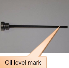
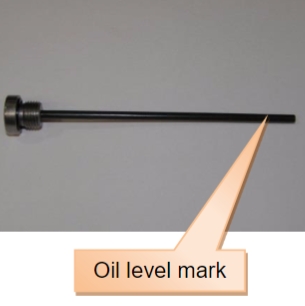
- CHECK OIL LEVEL WITH THE DIPSTICK PROVIDED IN THE SUPERCHARGER ASSEMBLY. TIGHTEN DIPSTICK FULLY AND THEN CHECK THE OIL LEVEL.
3. OIL LEVEL SHOULD BE CHECKED WITH THE DIPSTICK PERIODICALLY (RECOMMENDED EVERY WEEK AND ALSO BEFORE & AFTER A LONG JOURNEY).
Note:
1. Many of the photos shown in this document are of a typical Jeep- TJ Right hand drive vehicle and are similar to a typical Jeep- TJ Left hand drive vehicle.
2. Some of the terminology and language used in this instruction may vary from that of the end user / installer’s expectations, as some tools and automotive components have different common names in different geographical locations.
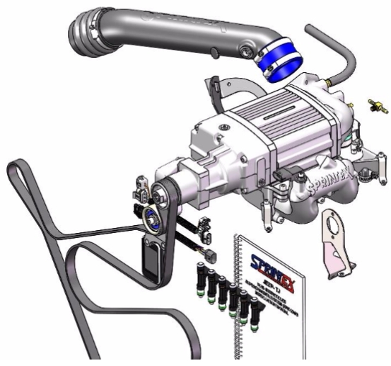
PARTS SUPPLIED
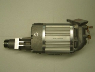
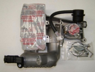
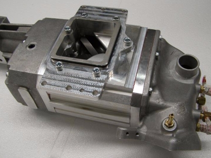
Supercharger assembly with air intake housing
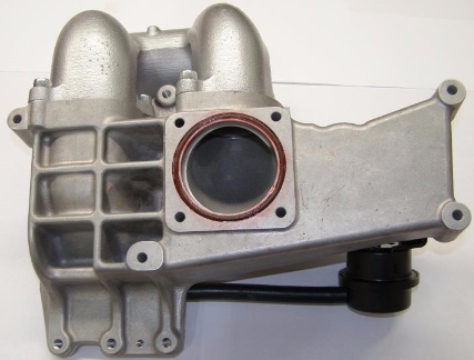
Discharge assembly
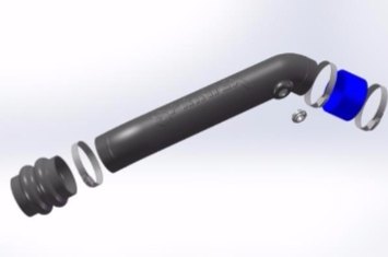
Inlet pipe assembly
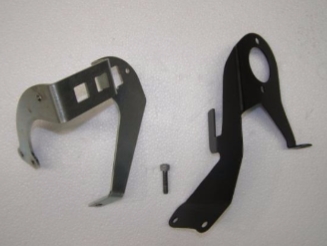
Throttle cable bracket assembly
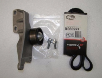
Idler pulley bracket assembly & drive belt
Ancillary parts assembly
Fuel injectors
ECU Reflash unit

JEEP- TJ SUPERCHARGER SYSTEM
(NON- INTERCOOLED)
SECTION 1
DISASSEMBLY INSTRUCTIONS
SAFETY WARNING
No unauthorised service or alteration may be undertaken to the Sprintex supercharger. Installation should be carried out in a workshop which is a safe and ventilated working environment with equipment and procedures compliant with local authority guidelines and legal requirements. Installers should ensure adequate hearing, eye, and physical protection is used at all times during the installation process. Installers should take reasonable precautions to avoid fatigue and closely follow the installation instructions during every installation. Sprintex recommends installation should not be carried out unsupervised. Sprintex, its directors, employees and agents will not accept liability for damage accident or injury resulting from the installation process. Safety warnings are also provided throughout this document.
Preparation
Ensure that all components required to assemble the supercharger are available. Refer to the Parts Supplied section provided earlier.
Ensure that all required tools are available.
Please read the entire instruction manual prior to beginning the installation procedure.
Ensure vehicle is located in a secure position with vehicle tyres secured and handbrake applied. Sprintex® recommends to avoid injury you should use a vehicle lift or axle stands when the vehicle is required to be lifted for access. Stands should be positioned as per the Manufacturers Owners Handbook.
SAFETY WARNING: Use Personal Protective Equipment such as safety glasses, gloves, etc. at all times and as necessary.
SAFETY WARNING: Allow engine to cool prior to proceeding with disassembly to prevent scalding.
SAFETY WARNING: The fuel system is under high pressure. Ensure to take care and follow procedures as mentioned in the vehicle’s workshop manual while working with the fuel system.
Note: During disassembly and removal of components, take notes and ensure to label and store them safely; this will help with the reassembly.
Note: Many of the photos shown in this document are of a typical Jeep- TJ right hand drive vehicle and are similar to a typical Jeep- TJ left hand drive vehicle.
Caution:
Connect and disconnect battery cables, jumper cables or battery charger only with the ignition switched off
Warning:
Disconnecting the battery may erase fault codes stored in control module memory.
Using diagnostic equipment, check for fault codes before disconnecting battery cables.
If the malfunction indicator light (MIL) is illuminated.
MIL (Malfunction Indicator Lamp) light.
The MIL light can be found in one of two locations, dependant on the market the vehicle has been built for.
1. The MIL light may be an illuminated ENGINE symbol within the speedometer cluster.
2. The MIL light may be displayed as SERVICE ENGINE SOON within the Revolution counter.
Please refer to your OWNERS HANDBOOK to define which of the above applies to your vehicle.
Note:
Always disconnect the negative battery terminal first. This prevents possible shorting and potential battery damage.
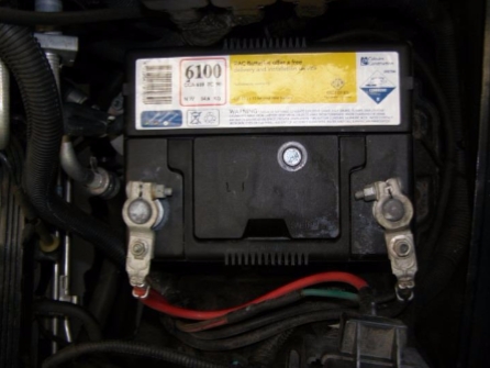
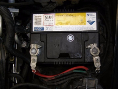
1. Disconnect Battery
The Jeep- TJ battery is located in the passenger side corner of vehicle (LH & RH drive).
1. First disconnect negative (-) battery cable.
2. Lift positive ( ) terminal plastic cover, then disconnect positive ( ) cable.
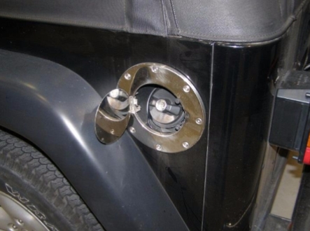
2. Loosen fuel filler cap
Loosen fuel filler cap to relieve pressure in the system.
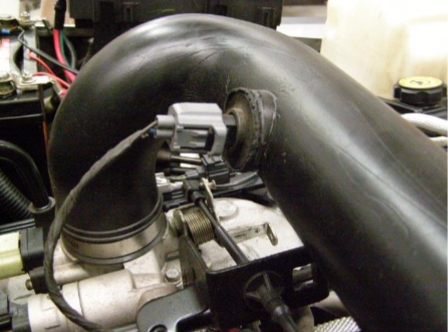
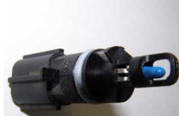
3. Disconnect air temp sensor from the air inlet pipe
1. Disconnect wiring to factory air temp sensor.
2. Remove factory air temp sensor and store in a safe location.
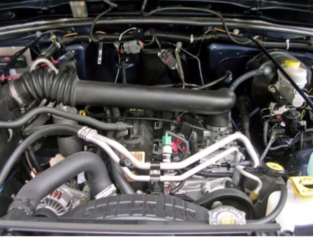
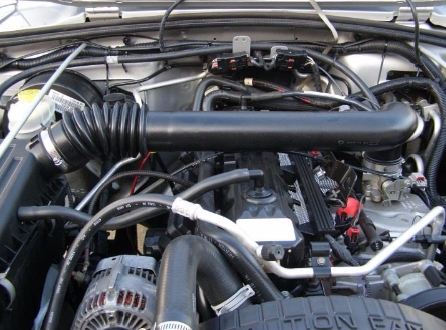
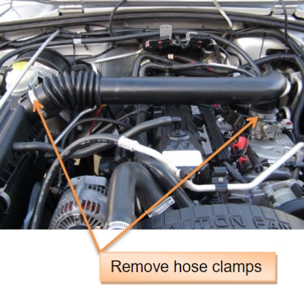
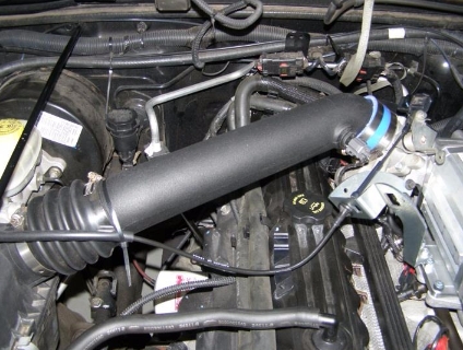
4. Remove air inlet pipe
1. Loosen hose clamps on each end of the pipe and remove the air inlet pipe.
2. Remove the hose clamps and store in a safe location.
3. Mask the air box outlet with sealing tape to avoid dirt and foreign particles entering the assembly.
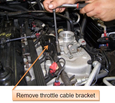
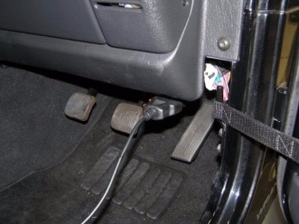
5. Remove throttle cable bracket
1. Disconnect throttle cable, optional cables like cruise control cable, line pressure cable (kick down cable) from the throttle cable bracket.
2. Remove 2x M6 SHCS screws, throttle cable bracket and store in a safe location.
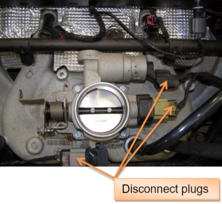
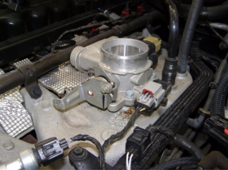
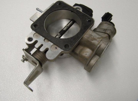
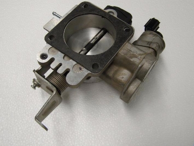
6. Remove throttle body and gasket
1. Disconnect wiring plugs from the throttle body.
2. Remove 4x M6 Hex head screws, throttle body with gasket and store in a safe location.
3. Seal the throttle hole with sealing tape to avoid dirt and foreign particles entering manifold.
NOTE: The gasket is re-used in the assembly at a later stage. So check the condition of the gasket and replace, if necessary.
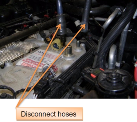
7. Disconnect engine breather and brake booster hoses
1. Disconnect Engine breather and brake booster hoses from the manifold.
2. Seal the manifold holes with sealing tape to avoid dirt and foreign particles entering manifold.
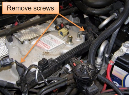
8. Detach cable conduit from the manifold
1. Remove two M6 x 20 Hex head screws and detach the cable conduit from the manifold and store the screws in a safe location.
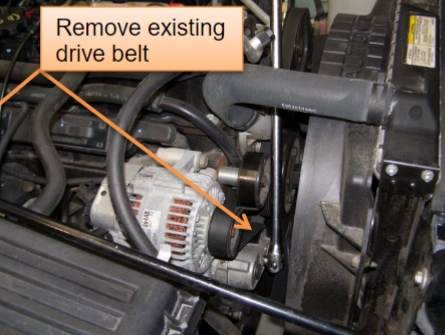
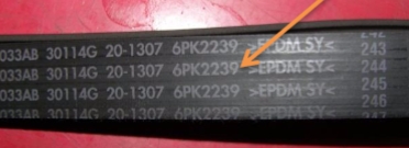
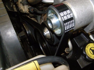
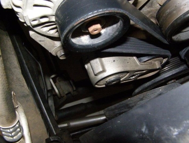
9. Remove engine accessory drive belt
Remove the drive belt using long series ½” breaker bar, to release the dynamic tensioner. Store the used belt in a safe location.
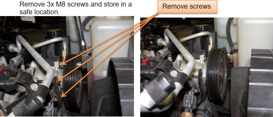
10. Remove 3 screws of the Power steering pump
Remove 3x M8 screws and store in a safe location.
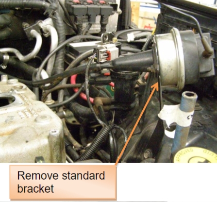
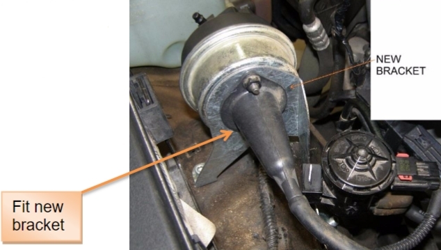
11. Replace Cruise control bracket (if equipped)
1. Disconnect wiring plug and hose from the cruise control unit
2. Remove 2 nuts and remove cruise control unit, cruise control cable from the standard factory steel bracket.
3. Remove carbon canister unit from the standard factory steel bracket.
4. Remove 3x M6 hex head screws and remove the factory steel bracket.
5. Fit the supplied new cruise control bracket with the previously removed factory screws.
6. Fit the cruise control unit, cruise control cable and carbon canister unit back into the new steel bracket.
7. Reconnect wiring plug and hose to the cruise control unit
JEEP- TJ SUPERCHARGER SYSTEM
(NON- INTERCOOLED)
SECTION 2
INSTALLATION INSTRUCTIONS
SAFETY WARNING
No unauthorised service or alteration may be undertaken to the Sprintex supercharger. Installation should be carried out in a workshop which is a safe and ventilated working environment with equipment and procedures compliant with local authority guidelines and legal requirements. Installers should ensure adequate hearing, eye, and physical protection is used at all times during the installation process. Installers should take reasonable precautions to avoid fatigue and closely follow the installation instructions during every installation. Sprintex recommends installation should not be carried out unsupervised. Sprintex, its directors, employees and agents will not accept liability for damage accident or injury resulting from the installation process. Safety warnings are also provided throughout this document.
ASSEMBLY
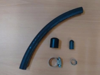
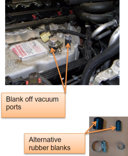
1. Blank off manifold Vacuum ports
1. Blank off vacuum ports for the engine breather, brake booster with the supplied 3/8” & 5/8” hoses, plugs and clamps.
2. Alternative rubber blanks might be supplied in the kit.
NOTE: If not using proper pliers damage can occur to the clamps.
WARNING: The fuel system is under high pressure fuel.
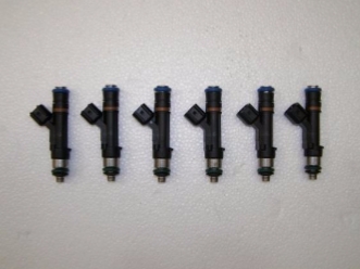
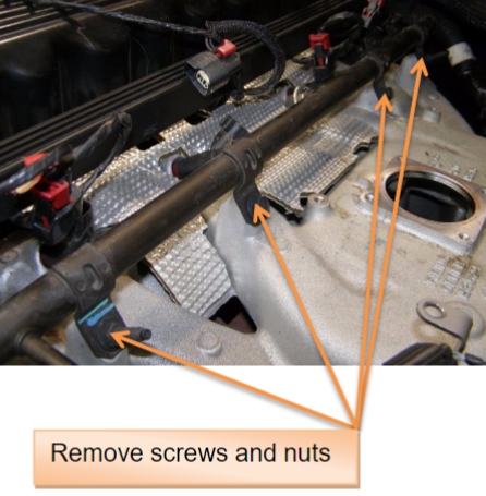
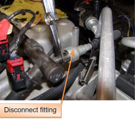
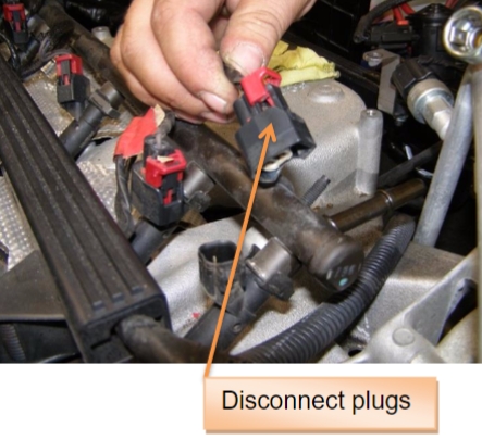
2. Replace fuel injectors
1. Disconnect fuel line fitting using fuel line removal tool
2. Disconnect plugs from the fuel injectors (6x)
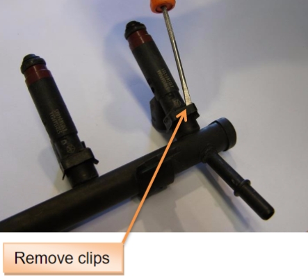
3. Remove fuel rail mounting screws (2x) and nuts (2x) and gently lift fuel rail assembly out.
4. Remove the injector retaining clips from fuel rail assembly.
5. Remove existing standard fuel injectors (6x) and store in a safe location.
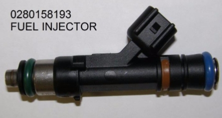
6. Fit new supplied fuel injectors 0280158193 (6x) and ensure orientation. Apply a thin layer of rubber grease to the O-Rings of injectors for ease of fitting.
7. Fit the retaining clips back to hold the injectors securely.
8. Fit the fuel rail back with previously removed standard screws and nuts.
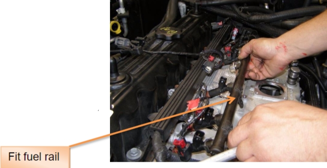
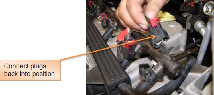
9. Connect the plugs back into the fuel injectors
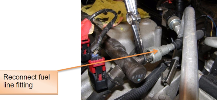
10. Reconnect the fuel line fitting to the fuel rail
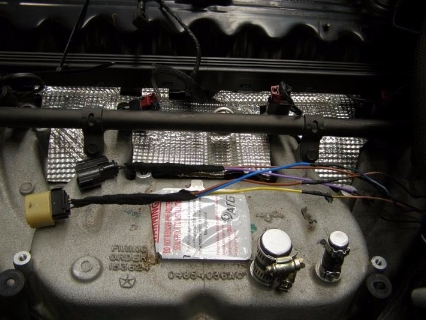
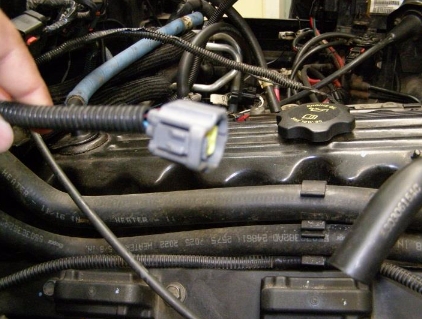
3. Extend the wires of TPS and IAC sensors (if necessary)
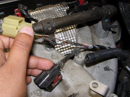
1. Carefully strip back wiring harness 50mm to separate TPS and IAC plugs.
2. Extend the wires of TPS plug with new wires (3x) supplied.
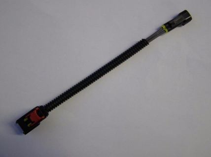
3. Connect standard IAC plug to the supplied plug extension.
4. Wrap the wires with the supplied split sleeve conduit and insulation tape.
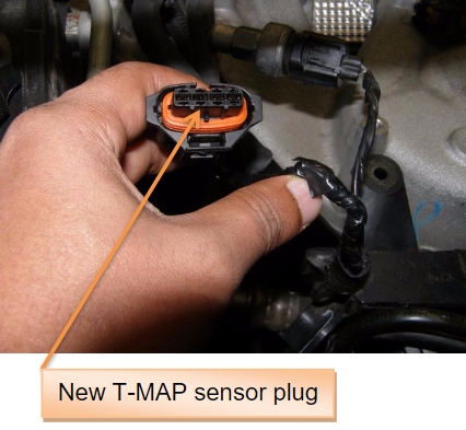
4. Connect the new T-MAP sensor plug
1. Cut the wires (3x) approx.50mm away from the standard MAP sensor plug. Remove the MAP sensor plug and store it in a safe location.
2. Splice the wires (3x) of the standard MAP sensor from the conduit with the supplied wires (3x) of the new T-MAP sensor plug. See the following information for details.
TMAP Connection info
TMAP TJ MAP wiring
1 => DB/DG
2 => No connect
3 => YL/PK
4 => VT/BR
On the plug tail, the colours and connections are as below,
Pin 1 (ground) Black, connect to Jeep Blue/ Green
Pin 2 (Temp) Blue , do not connect
Pin 3 (Power) Red, connect to Jeep Yellow/ Pink
Pin 4 (MAP Signal) Yellow, connect to Jeep Violet/Brown
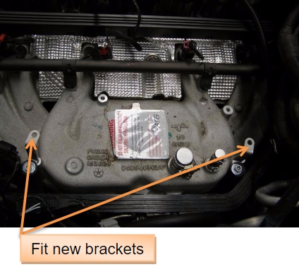
5. Fit cable conduit with supplied 2 steel brackets
1. Fit the supplied 2 steel brackets with the cable conduit using previously removed factory M6 Hex head screws and nyloc nuts (supplied).
2. Do not tighten the screw fully until the clamps are fitted to the discharge manifold at a later stage.
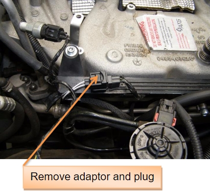
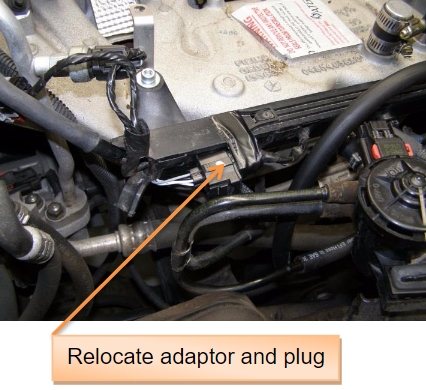
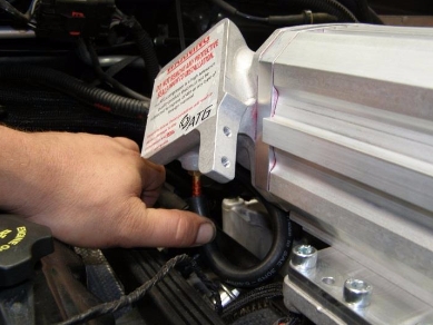
6. Remove adaptor with plug on the cable conduit and relocate
1. Remove the adaptor with plug from cable conduit and relocate as per the pictures given to clear the bottom side of the Supercharger discharge duct. Use cable tie to hold the adaptor with the conduit.
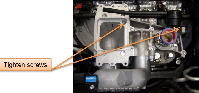
7. Fit discharge assembly to the manifold
1. Remove sealing tape from the bottom surface of the discharge manifold.
2. Apply rubber grease to O-Ring and fit it into the groove.
3. Clean the mounting surfaces on the vehicle manifold and carefully place the discharge assembly on top of the manifold as shown in the pictures.
4. Ensure that the assembly clears all hoses, cables, fuel rail and wirings.
5. Tighten the assembly with the provided SHCS M6 x 80 (torque to 11Nm)
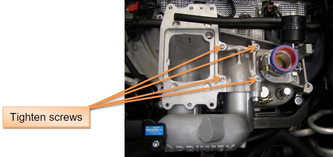
6. Mount the cable conduit with steel brackets (2x) to the discharge manifold and tighten using two M6 x 50 SHCS supplied (torque to 11Nm).
NOTE: Ensure that the cable
conduit clears manifold, discharge
manifold and discharge ducts.
7. Use other two M6 x 50 SHCS supplied and tighten the discharge manifold (torque to 11Nm).
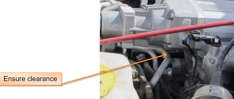
8. Bend the rear air-conditioner pipe (L/H drive vehicles only)
1. Using rubber mallet, carefully tap the rear air-conditioner pipe on top allowing it to lower by minimum 12mm from the original position.
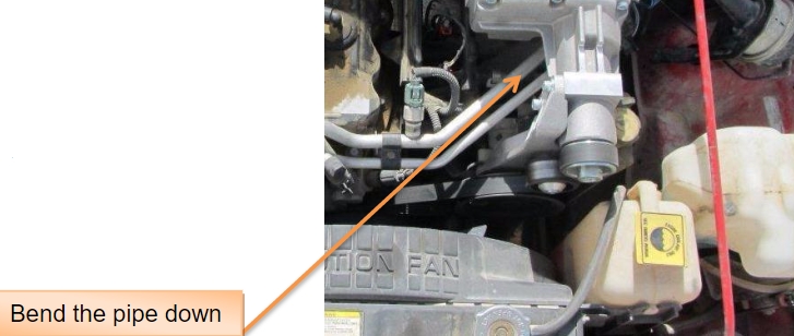
NOTE: Ensure that air-conditioner pipe is not damaged while trying to bend and also take special care to avoid the gas leak through the pipes and mountings.
NOTE: Ensure that the rear air-conditioner pipe clears the supercharger assembly.
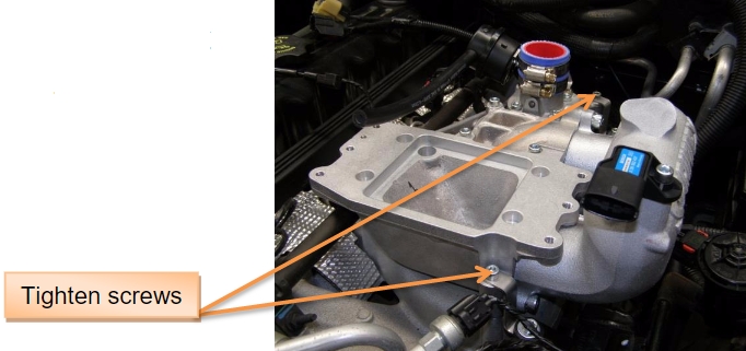
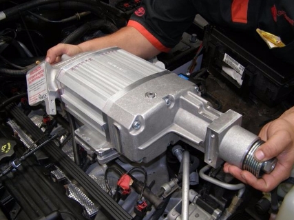
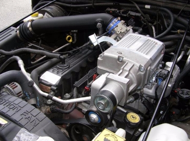
9. Fit Supercharger assembly to the discharge assembly
1. Remove sealing tape from the discharge outlet of Supercharger
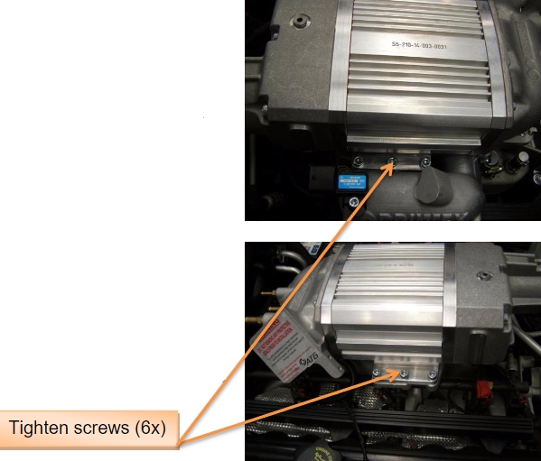
2. Fit the supercharger assembly (as supplied in the kit) into the discharge assembly and clamp them using six M8 x 25mm SHCS screws (torque to 23Nm).
3. Locate the spigots in the supercharger clamp plate and the intake housing carefully to avoid damage to the O-Ring and bypass hose.
NOTE: If required, apply a thin layer of rubber grease to the O-Ring and bypass hose for smooth fitting.
4. Tighten the top hose clamp for the bypass hose.
NOTE: Ensure orientation of the hose clamp to avoid interference with bypass actuator lever during operation.
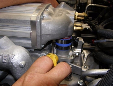
5. Connect the bypass actuator hose to the hose fitting in the intake housing.
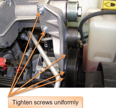
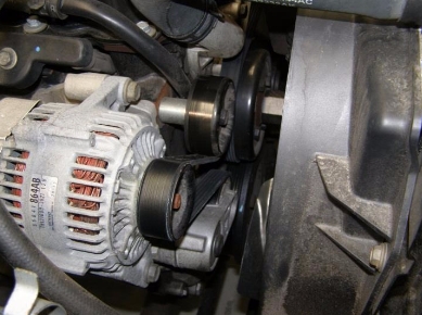
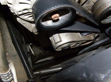
10. Fit Idler pulley bracket & power steering pump
1. Fit the idler bracket assembly using two M8 x 30 SHCS and flat washers provided.
2. Use the previously removed standard three M8 Hex head screws to mount the power steering pump and the idler pulley bracket as shown in the picture.
NOTE: Tighten all screws uniformly (torque to 23Nm).
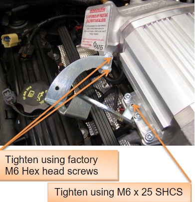
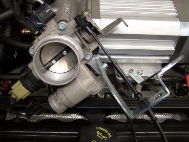
11. Fit new throttle cable bracket
1. Fit new throttle cable bracket supplied, using previously removed standard M6 Hex head screws (2x) into the intake housing (torque to 11Nm).
2. Tighten other side of the bracket using M6 x 25 SHCS (supplied) with the manifold (torque to 11Nm).
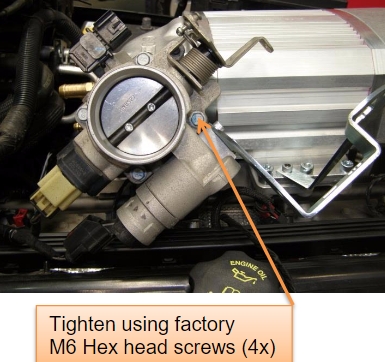
12. Fit throttle body
1. Connect TPS & IAC wiring plugs to the throttle body.
2. Fit the standard throttle body with the factory gasket using the previously removed factory M6 screws (4x). Torque to 11Nm.
3. Connect the throttle cable.
4. Connect the cruise control cable (if equipped) and kick down cable (if equipped).
5. Fit the factory MAP sensor back to the throttle body. Do not connect the wiring plug to the MAP sensor as it is replaced by supplied new T-MAP sensor.
NOTE: Check for free play of throttle cables.
13. Glue bayonet adaptor to the new air inlet pipe
1. Apply Loctite 406 on the flat surface of the bayonet adaptor and attach it to the new air inlet pipe as shown in the pictures. Ensure orientation.
2. For earlier model vehicles use the supplied blanking plug (grommet) instead of the bayonet adaptor, if necessary.
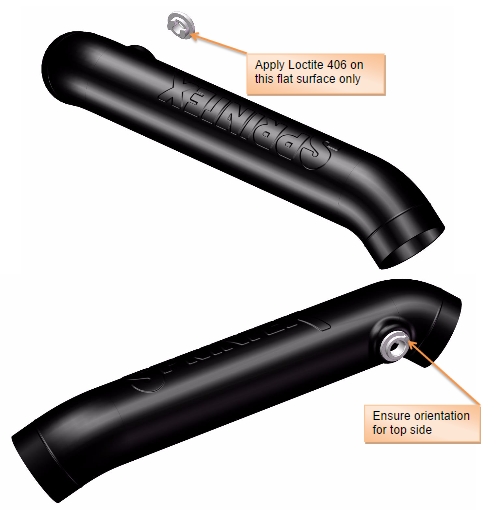
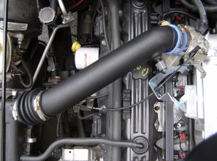
14. Fit new air inlet pipe
1. Connect new air inlet pipe between throttle body and air box. Secure with the hose clamps (3x) supplied. Use a hose clamp from the standard factory air inlet pipe.
NOTE: Ensure the orientation of the air temp sensor hole as shown in the picture.
15. Fit the factory air temp sensor
1. Fit the factory air temp sensor to new air inlet pipe.
2. Connect the wiring plug back to the air temp sensor.
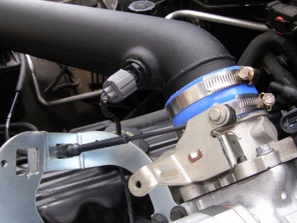
16. Hold the throttle cable in position
1. Hold the throttle cable in position with inlet pipe using a cable tie as shown in the picture.
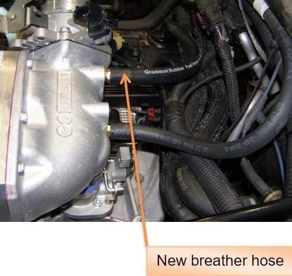
17. Fit breather and vacuum lines
1. Connect the engine breather, brake booster hoses to the intake housing as shown in the picture.
a. Use new supplied hose for engine breather
b. Use the existing standard hose for brake booster
NOTE: If necessary, use the supplied brass T- fitting (optional part) for additional vacuum ports. Apply Loctite 577 to threads of hose fittings and blanking plugs upon assembly.
18. Plug in electrical components
1. Connect the miscellaneous wiring plugs.
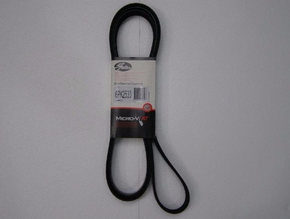
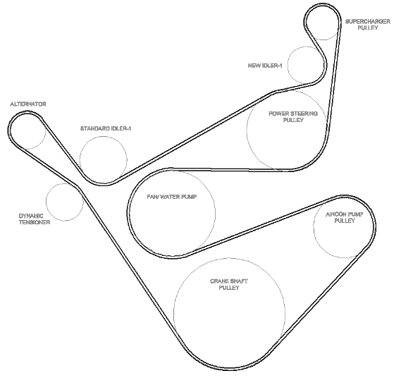
19. Fit new accessory drive belt
1. Fit new accessory drive belt 6PK2530 (Gates No.K060997) as per the belt routing diagram leaving the idler pulley as the last component for belt to be fitted over.
2. Use long series ½” breaker bar to release the dynamic tensioner.
BELT ROUTING DIAGRAM (WITH A/C)
20. Reconnect battery
NOTE: Battery Positive terminal should always be connected first.
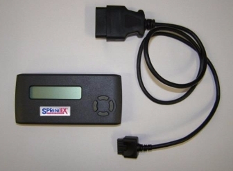
21. Load the ECM re-flash (Diablo tuner)
1. Read the instructions included with the Diablo SP2000 flash tuner.
2. Follow the instructions included with the Diablo SP2000 flash tuner.
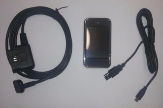
Hypertech tuner (if supplied)
1. Read the installation instructions included with the Hypertech tuner.
2. Follow the steps in the Hypertech tuner instruction manual.
3. Refer ‘Hypertech” website for more details and other functions.
NOTES:
It is critical during the programming process that the tuner doesn’t get interrupted. This could cause the vehicle computer to “crash”, and the vehicle to be inoperable.
Interruptions can be caused by a drop in battery voltage, causing the vehicle’s computer to cycle on and off, by accessories that communicate with the vehicle’s computer or by the programming cable being unplugged or not securely connected.
We recommend removing fuses for any aftermarket accessories that draw voltage from the battery.
JEEP- TJ SUPERCHARGER SYSTEM
(NON- INTERCOOLED)
SECTION 3
PRE TEST-DRIVE INSPECTION
Pre-Start Inspection
Ensure coolant is at correct level.
Ensure engine oil is at correct level.
Ensure vehicle has fresh 95 RON (91 Octane USA) Premium Unleaded fuel.
Ensure the belt is aligned.
Ensure the air filter is clean.
Check & replace spark plugs, if necessary. Set gap to factory spec. 0.035”.
SAFETY WARNING: Ensure adequate steps are taken to prevent injury, spillage or fire should any of the required installation steps not have been carried out to specification.
IMPORTANT NOTE!!
THIS SPRINTEX SUPERCHARGER SYSTEM REQUIRES THAT THE VEHICLE IS FITTED WITH AN APPROVED ECU AND ECU CALIBRATION. FAILURE TO ENSURE THIS WILL AFFECT THE PERFORMANCE AND MAY VOID THE WARRANTY. REFER TO THE SPRINTEX DEALER THAT SUPPLIED THE KIT FOR CONFIRMATION.
SPRINTEX RECOMMENDS THAT THE VEHICLE IS NOT RUN UNLESS A SUITABLE ECU CALIBRATION IS INSTALLED.
Engine Warm Up
Start engine and allow to run, until engine reaches normal operating temperature.
Check for oil leaks.
Road Test Vehicle
Road test vehicle.
Recheck all joints and connections for leaks –rectify as needed.
JEEP- TJ SUPERCHARGER SYSTEM
(NON- INTERCOOLED)
SECTION 4
MAINTENANCE INSTRUCTIONS
1. Supercharger Drive Belt Replacement
It is recommended that the supercharger drive belt be checked at every regular service and be replaced at 50,000 km (30,000 miles) or 2 years, whichever occurs first.
Use long series ½” breaker bar to release the dynamic tensioner and remove the belt.
2. Supercharger Removal
Refer to section 1
DISASSEMBLY INTRUCTIONS, Pages 12 to 16.
3. Supercharger Lubrication Service
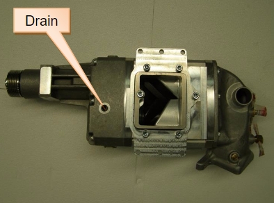
1. Drain and replace oil every 40,000 km (25,000 miles) or 2 years (whichever is earlier).
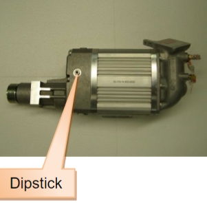
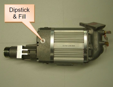
2. Place a suitable funnel under drain plug at front side bottom of Supercharger extension housing. Remove dip stick on top centre of cover to allow complete draining. Remove bottom plug and drain.
3. Fit the bottom drain plug back. Use Loctite 577 to threads upon assembly.
4. Supercharger is supplied with Redline 75W90 NS gear oil.
Fill with 157 millilitres or 5.31 US fluid ounces of Fully synthetic SAE 75W90 gear oil (Specifications: API GL5, MT-1).
5. Fit the dip stick back on top of the supercharger extension housing (torque to 10Nm).
NOTES:
1. Check oil level with the dipstick provided in the Supercharger assembly. Tighten dipstick fully and then check the oil level.
2. Oil level should be checked with the dipstick periodically (Recommended every week and also before & after a long journey).
4. Spark plugs
Replace spark plugs every 50,000 km.