 FREE 1 to 3-Day Delivery on Orders $149+ Details

How to Install Sprintex 3.8L Intercooled Supercharger System with Tuner on your Wrangler
Installation Time
4 hours
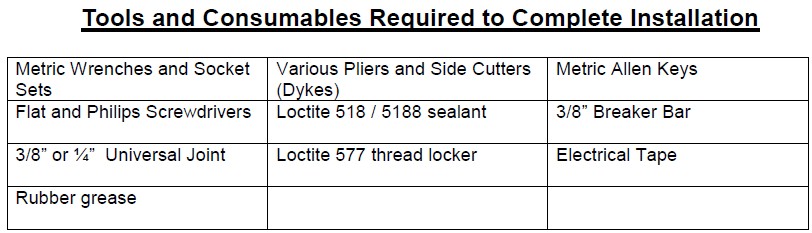
Tools Required
- Metric Wrenches and Socket Sets
- Flat and Philips Screwdrivers
- 3/8” or ¼” Universal Joint
- Rubber grease
- Various Pliers and Side Cutters (Dykes)
- Loctite 518 / 5188 sealant
- Loctite 577 thread locker
- Metric Allen Keys
- 3/8” Breaker Bar
- Electrical Tape
PARTS SUPPLIED
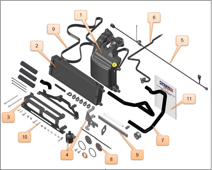
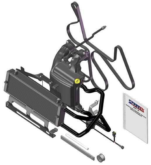
JEEP- JK (2007 - 2011) SUPERCHARGED INTERCOOLER UPGRADE KIT
SECTION 1
DISASSEMBLY INSTRUCTIONS
Preparation
Ensure that all components required to assemble the supercharger are available. Refer to the Parts Supplied section provided earlier.
Ensure that all required tools are available.
Please read the entire instruction manual prior to beginning the installation procedure.
Ensure the vehicle is located in a secure position with the vehicle tyres secured and the handbrake applied. To avoid injury, Sprintex® recommends use of a suitable vehicle lift or axle stands when the vehicle is required to be lifted for access to. Stands should be positioned as per the vehicle Manufacturers Owners Handbook.
SAFETY WARNING: Use Personal Protective Equipment such as safety glasses, gloves, etc. at all times and as necessary.
SAFETY WARNING: Allow engine to cool prior to proceeding with disassembly to prevent scalding.
Note: During disassembly and removal of components, take notes and ensure to label and store them safely. This will help with the reassembly process.
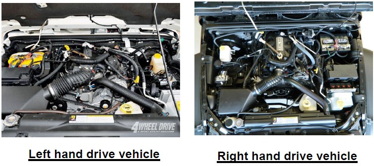
Note: Many of the photos shown in this document are of a typical Jeep- JK right hand drive vehicle and are similar to a typical Jeep- JK left hand drive vehicle.
Caution:
Connect and disconnect battery cables, jumper cables or battery chargers only with the ignition switched off
Warning:
Disconnecting the battery may erase fault codes stored in the control module memory.
Using diagnostic equipment to check for fault codes before disconnecting the battery cables.
If the malfunction indicator light (MIL) is illuminated.
MIL (Malfunction Indicator Lamp)
The MIL can be found in one of two locations, dependant on the market the vehicle has been built for.
1. The MIL may be an illuminated ENGINE symbol within the speedometer cluster.
2. The MIL may be displayed as SERVICE ENGINE SOON within the tachometer.
Please refer to the OWNERS HANDBOOK to define which off the above applies to the vehicle to be fitted with the Sprintex unit.
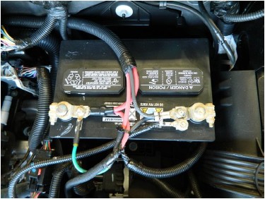
Note:
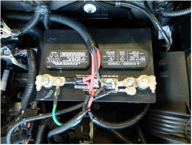
Always disconnect the negative battery terminal prior to disconnection the positive battery terminal. This prevents possible shorting and potential battery damage.
1. Disconnect Battery
First disconnect the negative (-) battery cable.
Lift the positive ( ) terminal plastic cover, then disconnect the positive ( ) cable.
2. Remove right side inner wheel well (LHD vehicles)- OPTIONAL
To assist access to EGR valve it may be beneficial to remove the passenger (right) side wheel and inner wheel well, (LHD VEHICLES ONLY) this step is not necessary but does make fitting components easier.
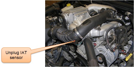
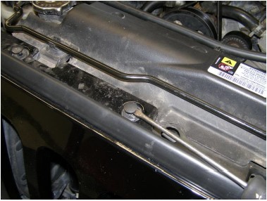
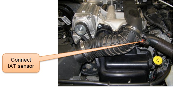
3. Remove factory air inlet hose
Unplug the IAT sensor & remove air inlet hose from the factory air box by loosening the hose clamps.
4. Remove plastic air inlet pipe
Disconnect breather hose and remove the plastic inlet pipe from the supercharger manifold.
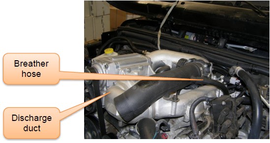
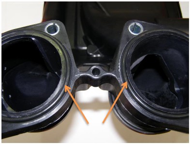
5. Remove discharge duct (Non-intercooled)
Loosen the compression fitting on the EGR pipe from the discharge duct.
Remove discharge duct by loosening the four M8 socket head screws and store in a safe location. These will not be used in the intercooler upgrade kit.
Seal the manifold openings with sealing tape to prevent dirt ingress.
6. Remove the existing EGR pipe
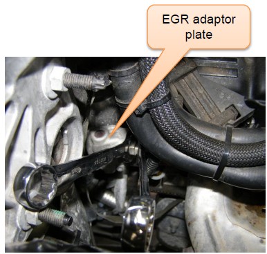
Loosen the rear EGR fitting from the EGR adaptor plate.
Remove EGR pipe from the EGR adaptor plate and store in a safe location. This will not be used in the intercooler upgrade kit.
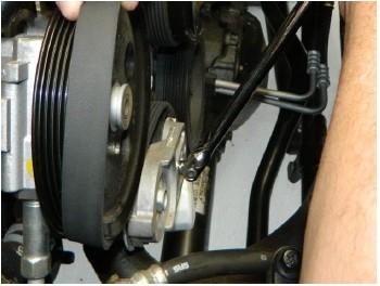
7. Remove drive belt
Use long series 3/8” breaker bar to release the dynamic tensioner and remove the belt and store in a safe location. This will not be used in the intercooler upgrade kit.
8. Remove air box
Remove the factory air box and store in a safe location.
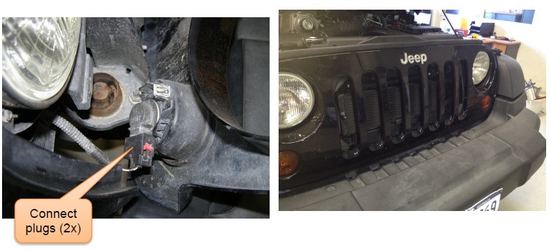
9. Remove the front grille
Use a pry tool or a flat blade screw driver to pull out the push pin rivets on the top side of the front grille
Carefully loosen the clips on the bottom side of the front grille
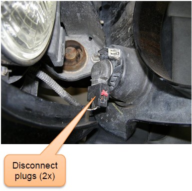
Disconnect the plugs (2x) from the turn signal lamps located behind the front grille
Remove the front grille and store in a safe location
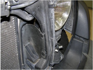
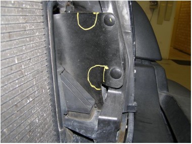
10. Modify plastic panel
Make a cut out (40mm wide x 40mm high), 2 places in the LHS plastic panel next to the factory radiator. This will allow the radiator hoses to pass through when the intercooler radiator is installed.
JEEP- JK (2007 - 2011) SUPERCHARGED INTERCOOLER UPGRADE KIT
SECTION 2
INSTALLATION INSTRUCTIONS
INTERCOOLER SYSTEM INSTALLATION
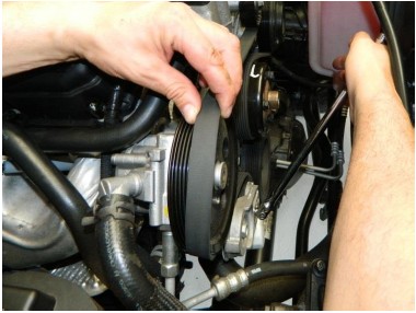
1. Swap the Supercharger pulley
NOTE:
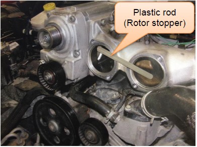
1. Do not apply more than 10Nm of tightening or loosening torque to the pulley mount screw while the plastic rod (rotor stopper) supplied is in the supercharger, as this may disturb the rotor alignment.
2. Take care to avoid dirt ingress into the supercharger.
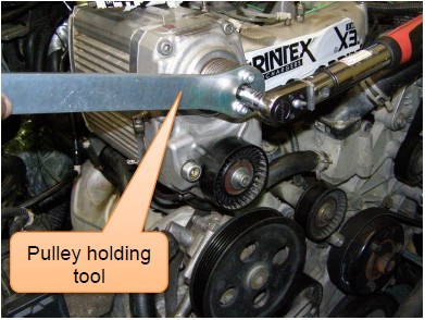
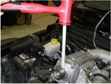
Loosen the SHCS retaining the supercharger pulley. Use the pulley holding tool supplied while loosening the screw.
OPTIONAL- Place the supplied plastic rod (rotor stopper) into the supercharger discharge side as per the picture stopping the rotors from spinning whilst removing the SHCS from the pulley because of Loctite on the screw threads.
Place the wedge (provided on one end of the rotor stopper) between the Supercharger and the pulley. Lightly tap on the wedge with a soft or rubber mallet. Rotate the pulley and repeat the process until the pulley comes off. Try not to remove the seal journal from the supercharger.
Clean Loctite residue from the pulley screw and inside the threaded hole
Thoroughly clean Loctite residue from the seal journal.
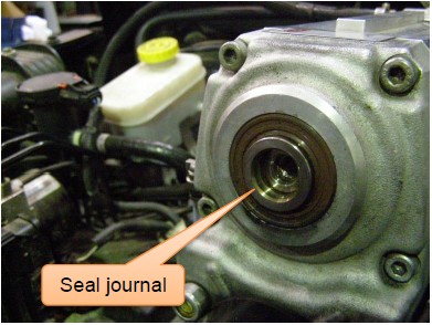
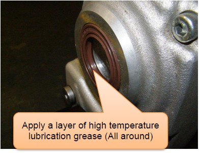
If the seal journal is removed accidentally from the supercharger, apply a layer of high temperature lubrication grease in between the lips of the lipseal. Insert the seal journal into the lipseal locating the spigot on the supercharger drive system.
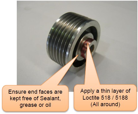
Apply a thin layer of Loctite 518 / 5188 or equivalent on the spigot of the new pulley
Install the new Ø50mm pulley supplied. Apply Loctite 518 / 5188 or equivalent to threads upon assembly. Tighten the pulley to 75Nm using the pulley holding tool supplied. While replacing the pulley, do not disturb or remove the seal journal (spacer) or lipseal from the supercharger.
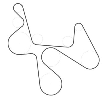
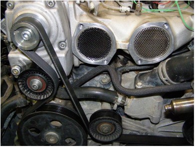
2. Fit the new drive belt
Fit the new supplied 6PK2666 (GATES No.K061049) Micro-V drive belt.
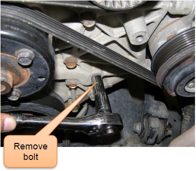
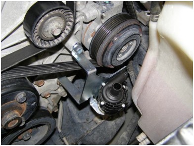
3. Fit the water pump mount bracket
Attach the water pump to the bracket using the cable- tie supplied, as shown in the picture below.
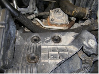
Remove the marked bolt from the engine.
Fit the water pump mount bracket to the engine using the previously removed bolt and the supplied SHCS M10 x 20.
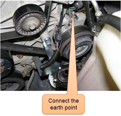
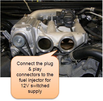
4. Attach the water pump wiring harness
Connect the water pump loom using the male & female connectors supplied, to one of the fuel injector connectors to provide switched 12V supply for the pump.
Connect the other end of the wiring harness to the water pump.
Connect the earth point as shown in the picture.
Secure the wiring harness using cable-ties supplied (3x) to avoid chafing on the moving parts.
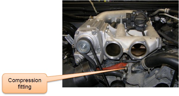
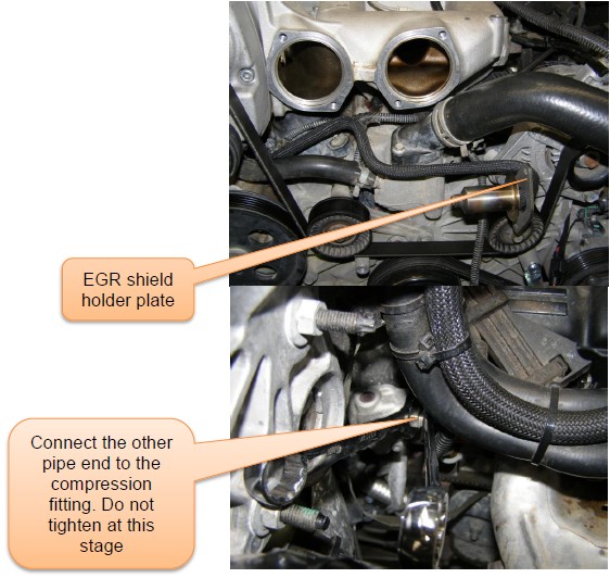
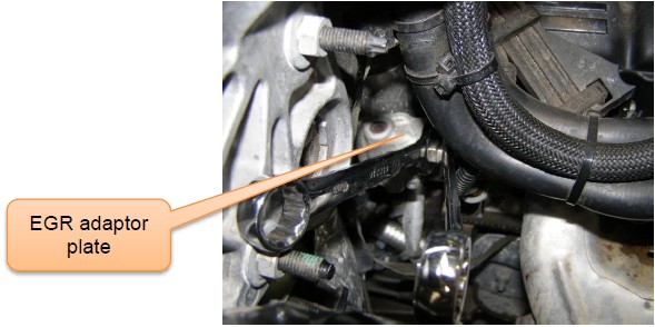
5. Position the EGR pipe (Intercooled kit specific)
Insert the EGR shield holder plate supplied. Ensure the braided sleeve is assembled to the EGR pipe
Position the EGR using the new compression fitting (Olive & nut), to the EGR adaptor plate, so that it can be accessed after the manifold is in place. Do not tighten the compression fitting at this stage.
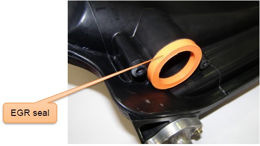
6. Fit the EGR seal/gasket to the Intercooler manifold
Fit the gasket supplied to the intercooler manifold.
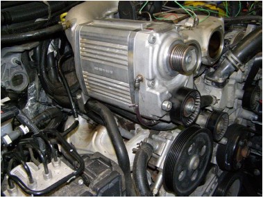
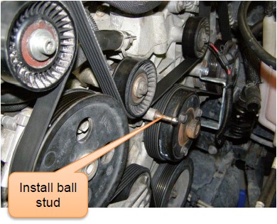
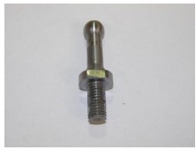
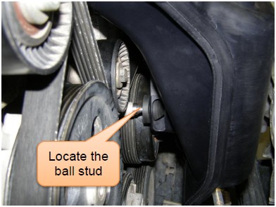
7. Installing the Intercooler manifold
Install the Ball stud supplied to the idler bracket as shown in the picture
Clean the discharge outlet holes of the manifold.
Place the two silencing plates supplied, into the manifold using a thin layer of grease to keep the plates in position.
Fit the two O-rings supplied to the intercooler manifold. Apply a thin layer of rubber grease to the O-Rings for ease of fitting.
Slide the intercooler manifold into place sideways, engaging the EGR pipe with the gasket
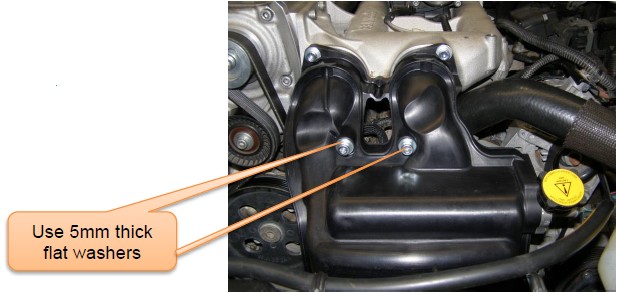
Locate the rubber grommet in the intercooler manifold to the ball stud. Carefully install into the discharge manifold. Take care not to damage the O-Rings upon installation. Fit the intercooler manifold using the supplied SHCS M8 x 30 (2x) with M8 flat washers (2x) and SHCS M8 x 120 (2x) with 5mm thick flat washers (2x). Tighten screws to 23Nm.
8. Tighten the EGR pipe to the Intercooler manifold
Centralise the EGR shield to the EGR seal and clamp it to the manifold, using the clamp plate and self-tapping screws supplied. Tighten to 6Nm.
NOTE: Ensure the EGR shield and the EGR pipe is not touching the plastic intercooler manifold.
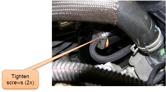
Tighten the compression fitting on the EGR adaptor plate.
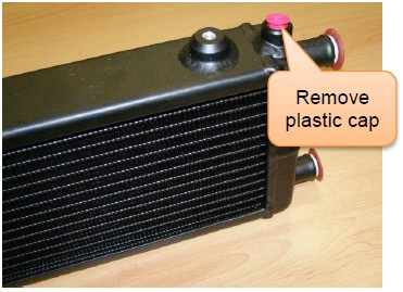
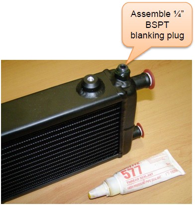
9. Intercooler radiator preparation
Remove plastic blanking cap
Apply thread sealant (Loctite 577 or equivalent) to the supplied ¼” BSPT blanking plug. Assemble the plug to the radiator and tighten adequately.
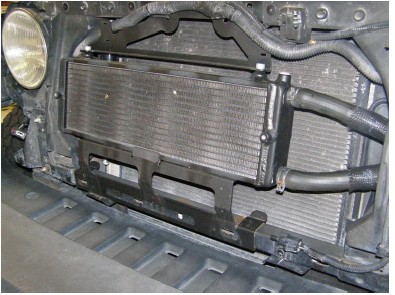
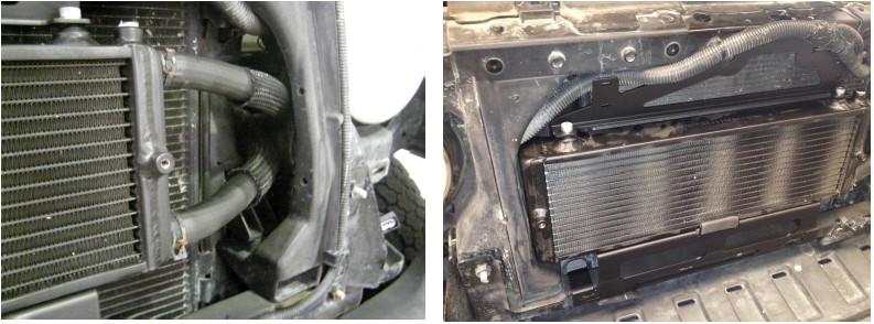
10. Fit the intercooler radiator
Connect the radiator hoses (2x) to the radiator and fasten using the spring clamps supplied. Refer picture for the hoses orientation.
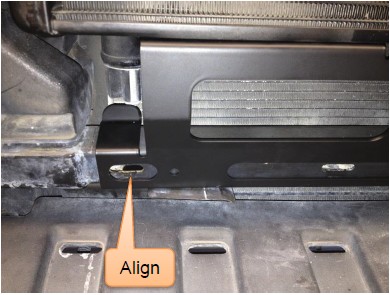
Locate the bottom bracket to the vehicle’s frame aligning the slots as shown in the picture.
Locate the intercooler radiator to the bottom bracket.
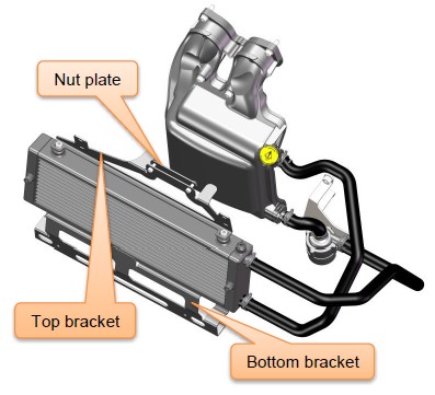
Fit the top bracket to the intercooler radiator using the supplied Hex head bolt M8 x 12 (2x) with M8 flat washers.
Tighten the top bracket of the intercooler radiator to the frame as shown in the pictures using the supplied SHCS M6 x 20 (2x) and radiator mount nut plate. Ensure the assembly is securely mounted and that adequate clearance remains between the air-con condenser and intercooler radiator.
Align the radiator on the brackets and tighten all fasteners.
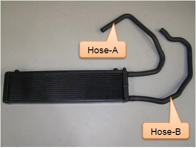
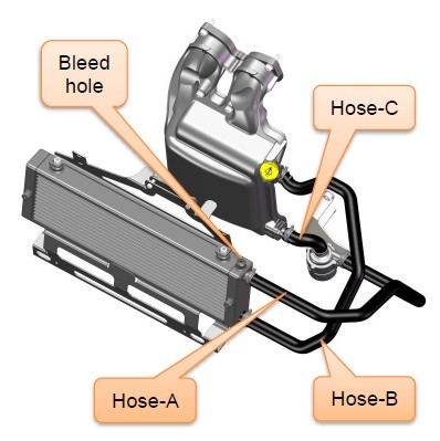
11. Connect Hoses
Use the 150mm long braided sleeving supplied (3x) to prevent the intercooler hoses from chafing on the OEM overflow bottle, vehicle front panels and the LHS plastic panel next to the radiator.
Attach Hose-A to the water pump outlet and route the other end beside the engine radiator and to the top hose connection of the radiator.
Attach Hose-B to the intercooler inlet hose connection (top) and route the other end beside the engine radiator and to the bottom hose connection of the radiator.
Attach Hose-C between the intercooler outlet hose connection (bottom) and the inlet of the water pump.
Fasten all the hose connections with the hose clamps supplied.
OPTIONAL- Remove the blanking plug from the bleeding hole of the intercooler radiator before filling the coolant.
Fill the intercooler system with 1350ml (46 fluid oz.) of ethylene glycol based automotive engine coolant approved for use in aluminium engines. Allow the system to bleed.
Once the coolant reaches the intercooler radiator, fit the previously removed blanking plug. Use Loctite 577 to threads upon assembly.
Repeatedly squeeze the hoses to help to remove any air present in the system.
Temporarily connect the battery. Turn the ignition to the run position and start the engine. Confirm that the intercooler water pump is running.
With the pump running, continue to fill the system until all of the 1350ml of coolant is used. This step is important as the intercooler will perform poorly and restrict the engines performance if air remains in the system. It may be necessary to run the vehicle or ‘work’ (squeeze) the hoses some more to eliminate all air from the system.
Check the intercooler coolant level & top up if necessary
Check all the intercooler hose connections for leaks.
Disconnect the battery again.
12. Fit the factory air box
Fit the factory air box to the vehicle.
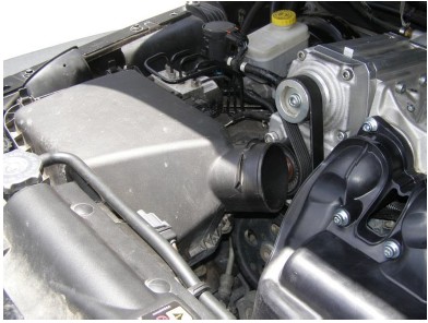
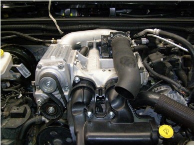
13. Fit the air inlet Pipe and the factory air inlet hose
Reattach the air inlet pipe to the throttle body and fasten using hose clamp.
Reconnect the engine breather extension hose to the inlet pipe.
Reattach the factory air inlet hose to the air inlet pipe and air box. Fasten using hose clamps.
Connect the IAT sensor to the air inlet hose.
14. Fit the front grille
Connect the plugs (2x) to the turn signal lamps behind the front grille
Carefully locate & press the clips on the bottom side of the front grille to the frame.
Insert & lock the push pin rivets on the top side of the front grille to the frame.
15. Reconnect the Battery
Reconnect the battery.
NOTE: The battery positive terminal ( ) should always be connected before the negative terminal (-).
16. ECU Reflashing
Refer to instructions included for re-flashing the ECU.
JEEP- JK (2007 - 2011) SUPERCHARGED INTERCOOLER UPGRADE KIT
SECTION 3
PRE TEST- DRIVE INSPECTION
SAFETY WARNING
Ensure adequate steps are taken to prevent injury, spillage or fire.
1. Pre-Start Inspection
Ensure the coolant is at the correct level.
Ensure the engine oil is at the correct level.
Ensure the vehicle has fresh 95 RON (91 Octane USA) premium unleaded fuel or higher.
Ensure the belt is aligned.
Ensure the air filter is clean.
Check & replace spark plugs if necessary. Set the gaps to factory spec.
SAFETY WARNING: Ensure adequate steps are taken to prevent injury, spillage or fire, should any of the required installation steps not have been carried out to specification.
IMPORTANT NOTE!!
THIS SPRINTEX SUPERCHARGER INTERCOOLER UPGRADE INSTALLATION REQUIRES THAT THE VEHICLE IS FITTED WITH AN APPROVED ECU AND ECU CALIBRATION. FAILURE TO ENSURE THIS WILL AFFECT THE PERFORMANCE AND MAY VOID THE WARRANTY. REFER TO THE SPRINTEX DEALER THAT SUPPLIED THE KIT FOR CONFIRMATION.
SPRINTEX RECOMMENDS THAT THE VEHICLE IS NOT RUN UNLESS A SUITABLE ECU CALIBRATION IS INSTALLED.
2. Engine Warm Up
Start the engine and allow it to run until it reaches normal operating temperature.
Check for leaks.
Check the intercooler filler coolant level with the engine running and top up the system with the remainder of the 1350 ml of coolant if required. If the system does not take the full 1350 ml of coolant there must be an air lock in the system. Top up the system once the vehicle has been taken for a short test drive.
Check the engine coolant level & top up if necessary.
3. Road Test Vehicle
Road test the vehicle.
Recheck all joints and connections for leaks & rectify as required.
Check intercooler system coolant level.
JEEP- JK (2007 - 2011) SUPERCHARGED INTERCOOLER UPGRADE KIT
SECTION 4
MAINTENANCE INSTRUCTIONS
1. Supercharger Drive Belt Replacement
It is recommended that the supercharger drive belt be checked at every regular service and be replaced at 50,000 km (30,000 miles) or 2 years, whichever occurs first.
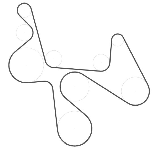
Use long series 3/8” breaker bar to release the dynamic tensioner and remove the belt.
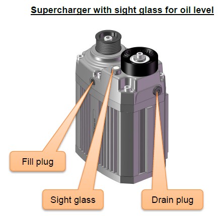
2. Supercharger Lubrication Service
1. Drain and replace oil every 40,000 km (25,000 miles) or 2 years (whichever is earlier).
2. Place a suitable funnel under drain plug at front side bottom of Supercharger extension housing. Remove the blanking plug on top centre of cover to allow complete draining. Remove bottom plug and drain.
3. Refit the bottom drain plug.
4. Replenish with 134ml or 4.53 US fluid ounces of REDLINE 75W90 NS GEAR OIL or Equivalent.
5. Apply Loctite 577 to threads and refit the fill plug.
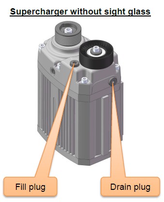
NOTE:
1. Oil level should be checked at the fill plug at every general service. Oil level should be at the bottom of the fill point, with the supercharger installed to the vehicle (fill to spill) (or) Check the oil level in the sight glass (if equipped).
2. Oil level should be checked periodically (Recommended every week and also before & after a long journey).
3. Supercharger Service
Sprintex recommends that the supercharger be serviced every 150,000 km. This entails a replacement of all bearings and seals.
