 FREE 1 to 3-Day Delivery on Orders $149+ Details

How to Install a SkyJacker 2.5 in. Value Flex Lift Kit w/o Shocks on your 2003-2006 Wrangler TJ Rubi
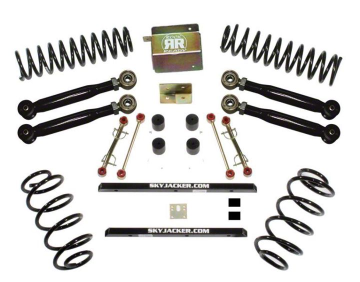
Shop Parts in this Guide
Before beginning the installation, thoroughly & completely read these instructions & the enclosed driver’s WARNING NOTICE. Affix the WARNING decal in the passenger compartment in clear view of all occupants. Please refer to the Parts List to insure that all parts & hardware are received prior to the disassembly of the vehicle. If any parts are found to be missing, contact SKYJACKER® Customer Service at 318-388-0816 to obtain the needed items. If you have any questions or reservations about installing this lift kit, contact SKYJACKER® Technical Assistance at 318-388- 0816.
Due to the inconsistency of vehicles when manufactured and the various options available, the amount of actual lift gained by this lift kit will vary.
IMPORTANT NOTES:
• 6-Speed Transmission models may require additional modifications, contact Skyjacker at 318-388-0816 for additional information.
• On models outfitted with extra bolt-on equipment & accessories, SKYJACKER® offers new coil spring isolator pads made from polyurethane to boost ride height 3/4", front or rear (order part # SIP275, pair).
PRE-INSTALLATION NOTES:
• A professional mechanic is recommended to perform the installation.
• Read the instructions carefully & study the photo illustrations before attempting the installation.
• Secure & properly block the vehicle on a level concrete or asphalt surface.
• Always wear safety glasses.
Front Installation:
1. Secure & properly block the rear tires / wheels of the vehicle on a level concrete or asphalt surface.
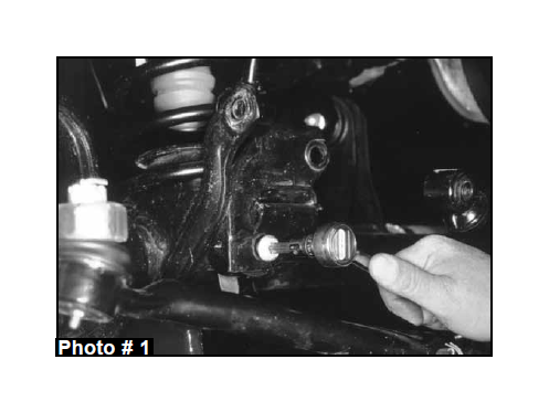
2. Raise the front of the vehicle & install jack stands under the frame behind the lower link rear brackets. Remove the front tires / wheels & front shocks. Remove the steering damper & remove the track bar from the passenger side axle & driver side frame. It may be necessary to pry loose. (See Photo # 1)
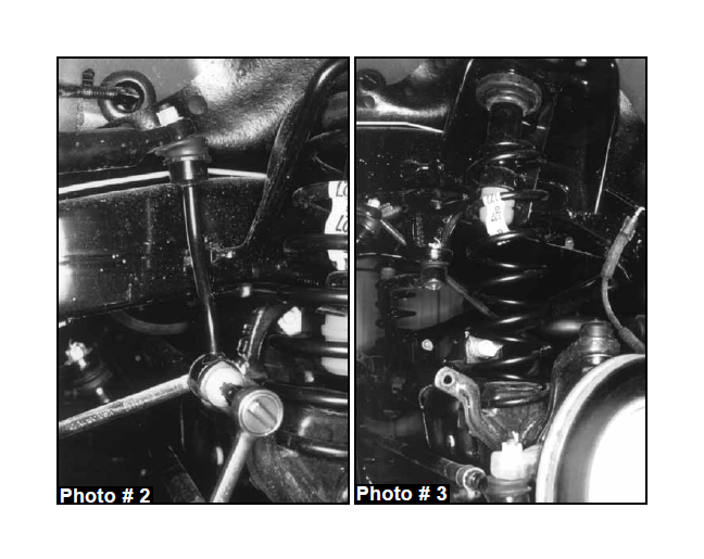
3. Remove the drag link assembly from the pitman arm & lower it down. (For 4" lifts, remove the pitman arm also.) Remove the sway bar end link's lower bolt at the axle housing on both sides. (See Photo # 2) Lower the front axle down until the coil springs become loose. Remove the bottom bolt & clip from the left front coil spring. (See Photo # 3) Install the new polyurethane tie rod dust covers.These will install on each end of the drag link & tie rod.
4. Remove both coil springs & remove the upper bump stop. (Use channel lock pliers working the bump stop back & forth).
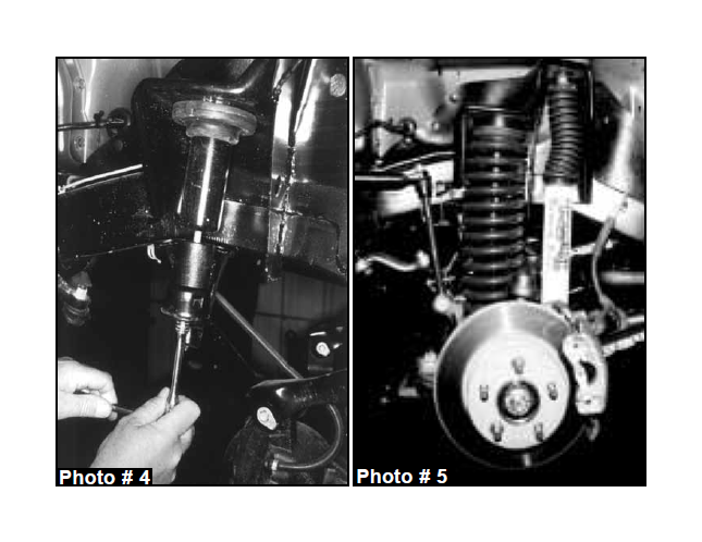
21/2" Lifts: Remove the bolt from the inside bump stop cup. Install the bump stop spacer & original cup using the supplied 10mm x 13/4" long bolts. Reinstall the OEM bump stop. (See Photo # 4)
4" Lifts: Install the new red poly-urethane longer bump stops.
5. Install the new coil springs & raise the jack up so enough load is applied to hold the coil springs in place. Reinstall the spring bolt & clip at the bottom of the left front coil.
6. Install the new shocks. (See Photo # 5) On 4" lifts, install the new drop pitman arm at this time. Reinstall the drag link to the pitman arm & tighten. (Be sure to install the cotter pin). Install the front tires / wheels & lower the vehicle to the ground.
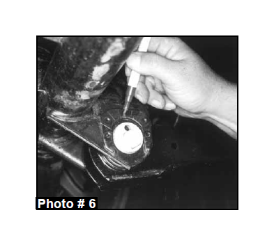
7. At the front lower link adjustment cams, mark (with an ink marker, or scribe a mark) the vertical line on the cam & the reinforcement bracket for reference so you can realign the marks after installation. (See Photo # 6)
8. "Set" the length of the new Flex Series link assemblies.
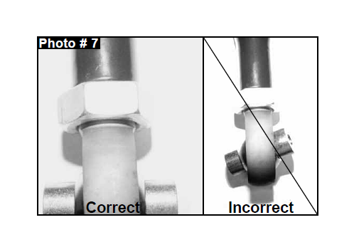
A) It is very important to position the swivel ball socket so that the bushings are exactly centered. (See Photo # 7)
B ) Measure the length of the link assembly between the center of each eye on each end. Rotate the rod end as needed, being sure to keep the ends square with each other until the link assembly measures: Lower Front & Rear should be 16 1/16".
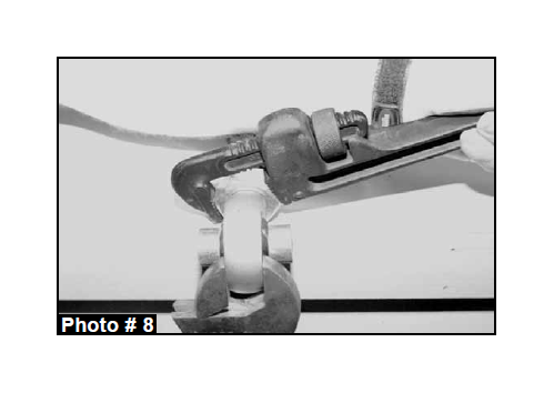
C ) On the rod end, rotate the jam nut against the steel tubing. Hold the rod end in place with a crescent wrench & using a pipe or crescent wrench on the jam nut, completely tighten. NOTE: Jam nuts must be tight against the steel tubing before installation.
D ) Recheck the center-to-center measurement to be sure it is correct & that the ends are square with each other.
IMPORTANT: Under no circumstances should the rod end (heim) be adjusted out more than 1/2" (including the jam nut) from the steel tubing of the link assembly!
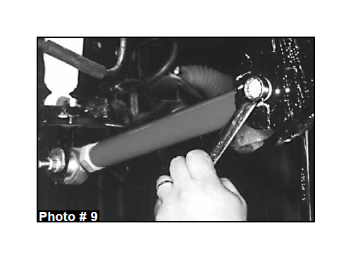
9. Remove & replace the lower links with the new Skyjacker® Flex Series links. Only start these bolts & nuts, do not tighten at this time. (On Single Flex Lower links, the adjustable rod end is installed at the axle.) Once all links are installed, tighten each link being sure to realign the marks on the eccentric cams. (See Photo # 9)
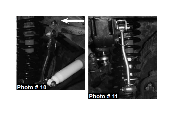
10. Install the new sway bar end links. The new end link mounting bracket should be mounted to the bottom of the sway bar with the bolt pointing up through the sway bar & the nut & washer applied on top. (See Photo # 10) Apply lithium grease to the metal sleeves & insert them into the end link eyes. The top 1/2" x 2 1/2" bolt connecting the bracket to the end link must be installed with the nut to the outside of the vehicle to provide adequate clearance to the frame. Install the new double disconnect end links on the inboard side of the axle bracket. (See Photo # 11)
11. 21/2" Lifts: Reattach the track bar in the OEM axle mount. (It may be necessary to rotate the steering wheel left or right to align the bolt hole.)
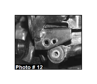
4" Lifts: Locate the front track bar mounting bracket on the axle, measure straight across to the right (inward) 3/4" & put a mark. Center punch & drill a 7/16" hole through both front & back plates, keeping the drill as straight & square to the bracket as possible. (See Photo # 12) Reattach the track bar. (It may be necessary to rotate the steering wheel left or right to align the bolt hole.)
12. Place a jack under the transfer case cross member & remove the four screws that mount the transfer case pivot assembly from the body of the vehicle. (It will be necessary to roll the floor mat back to gain access to the bolts.)
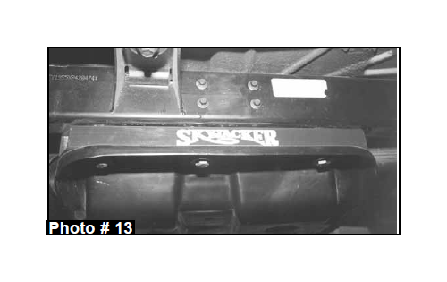
13. Remove the three bolts on each side of the transfer case skid plate & lower down enough to install the new square tube spacers between the skid plate & frame. 1997- 02 models use the flat socket head tapered bolts supplied. (2003 models will use the 12mm bolts & washers supplied). Also apply a few drops of supplied thread lock compound on the bolt threads prior to installing. Tighten bolts to 75-80 ft.lbs. (See Photo # 13)
* On 2003 models, also remove the two engine skid plate bolts. Install the small square tube spacers at the mounting points on the frame rails, along with the 12mm bolts supplied. 2.5” kits will use the 1” square tube spacers. 4” kits will use the 1.5” spacer.
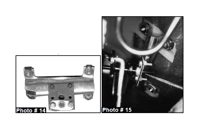
14. Install the new transfer case linkage pivot drop bracket to the OEM pivot bracket using the OEM screws. Using the supplied 1/4" x 1" bolts, washers, & nuts, bolt the ball swivel bracket to the new drop bracket. (See Photo # 14) (The bracket has two sets of holes: the bottom holes are for a 4" lift as shown, or next to the bottom for a 21/2" lift.) Placing the pivot bracket back in location, start the end of the rod thru the ball swivel & bolt the bracket back into location with the OEM hardware. (See Photo # 15)
Rear Installation:
15. Place a floor jack under the rear axle & raise the vehicle. Place jack stands under the frame ahead of the lower link bracket to support the vehicle & remove the rear tires / wheels & rear shocks.
16. Remove the rear track bar & sway bar end link bolts at the axle housing. Lower the rear axle down to remove the coil springs.
17. After removing both coil springs, remove the bump stops. (It may help to use channel lock pliers working the bump stop back & forth.) Remove the10mm bolt from inside the bump stop cup. Install the bump stop spacer & OEM cup using the supplied 10mm bolts. Reinstall the OEM bump stop. Optional poly bump stops like the front are available on 4" lifts, order Part # BP50.
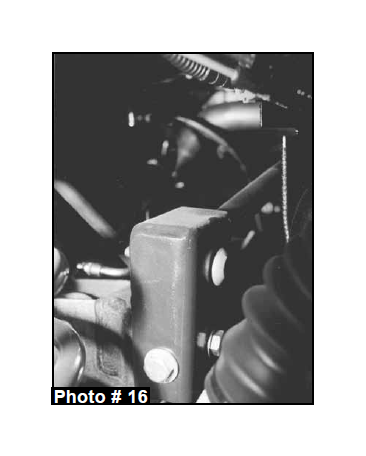
18. Place the new rear track bar relocation bracket in position & place the track bar in the new bracket. (Do not start its bolt) Start the new 12mm x 70mm bolt thru the OEM track bar location using the supplied spacer sleeve (# 54314) with a self-locking nut. Tighten at this time. Drill a 1/2" hole thru the hole in the end of the new bracket. Remove the 12mm x 70mm bolt, installed before drilling & install a /2 x 11/2" bolt, with a washer on each side, thru the new drilled hole & tighten with a self-locking nut. (See Photo # 16) Reinstall the new 12mm x70mm bolt thru the OEM track bar location using the supplied spacer sleeve (# 54314) with a selflocking nut & tighten. Do not bolt up the track bar, you must wait until the vehicle is on the ground.
19. Install the new coil springs. Raise the jack up so enough load is applied to hold the coil springs in place.
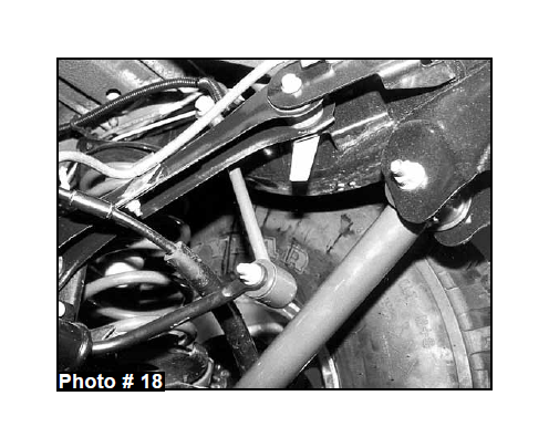
20. Remove & replace the lower links with the new Skyjacker Flex Series links. Only start these bolts & nuts, do not tighten at this time. The Single Flex Lower links are installed with the adjustable rod end at the axle. Once all links are installed, tighten each one. (See Photo # 18)
21. Assemble the new rear extended sway bar end links by applying grease to the metal sleeves & inserting them into each eye. Install using the OEM hardware. (See Photo # 18)
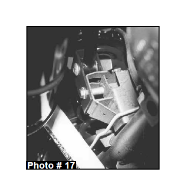
22. Install the new rear shocks, rear tires / wheels, & lower the vehicle to the ground. Bolt the track bar to the new relocation bracket using the OEM hardware. (See Photo # 16 & # 17) Also, be sure the OEM upper track bar bolt is tight.
WARNING: On these Wrangler TJ Jeep models, only the shock absorbers limit the extended position of the front & rear suspension! The use of shocks other than those supplied in this system, may cause coil disengagement, adverse steering angles, brakehose failure, driveline component failure, & / or other related component failure! The use of other shocks will void your Skyjacker® warranty!
FINAL NOTES:
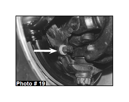
• Check the clearance between the inner side wall of the tires & links. It may be necessary to adjust the steering stops (By adding 2-3 washers on the bolt) to eliminate interference. (See Photo # 19)
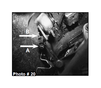
• Check the transfer case shifter to see if it will move to 4L. If not, the linkage will need adjusting as follows. Place the shifter in 4L, loosen the adjustment bolt ("A" Arrow in Photo # 20) & push the linkage ("B" Arrow in Photo # 20) forward until it stops. Retighten the adjustment bolt. Check to be sure the 4WD works properly.
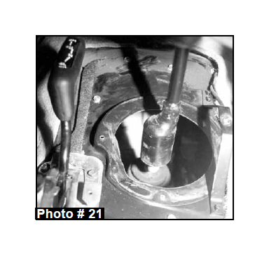
• On 5 speed models, engage the clutch & check the transmission shifter to see if it will go into 2nd gear. If not, the shifter housing on the floor will need trimming. Remove the center console, pull the back carpet, remove the screws holding the shifter boot to the floor board, & trim or grind the floor board until sufficient clearance is obtained. (See Photo # 21) Shift thru each gear to check for clearance at this time. Reinstall the boot, carpet, & console.
• A front end realignment is necessary after the lift is installed, have a qualified alignment center realign the front end to the OEM specifications.
• Rotate the driveshafts & check for interference at the differential yoke & cardan joint. If necessary, lightly dress the casting & / or U-joint tabs in order to eliminate binding.
• Ensure there is adequate clearance between the exhaust, brakelines, fuel lines, fuel tank, floor board, & wiring harnesses. Check the steering gear for interference & proper working order. Inspect the brakelines for damage & adequate clearance. Test the brake system before driving.
• With the vehicle on the ground, cycle the steering lock to lock & inspect the steering, suspension, driveline, & brakeline systems for proper operation, tightness, & adequate clearance.
• Have the headlights readjusted to the proper settings.
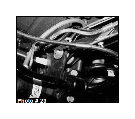
• If you purchased the Skyjacker® TJ rear driveline cam-bolt kit (Part # CAM500) install the kit as follows. Remove the bolt in the rear upper link (The end toward the rear bumper) & raise the link up out of the mounts.
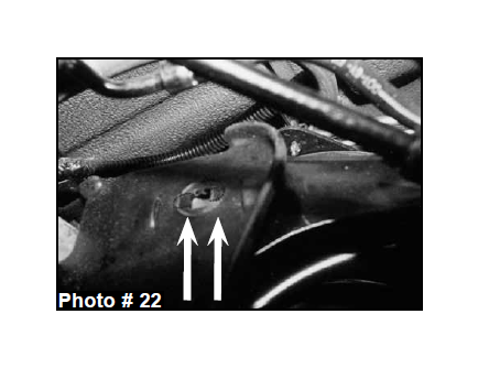
Note: The hole is notched so it can be a slotted hole. Knock out the notches on the front & rear half of the holes on each side of the link mounts. (See Arrows in Photo # 22) Repeat on the other side.
Lower the links back into the mounts. Install the new eccentric cam-bolts, eccentric washers, & nuts on each link & tighten. These bolts can be rotated to adjust the axle pinion angle to eliminate any driveline vibration.
Driveline vibrations can be caused from the removal or addition of the hardtop which changes the rear vehicle weight & the rear height which affects the rear drive shaft pinion angle. This cam-bolt will eliminate such vibrations by rotating the axle correcting the angle.(See Photo # 23)
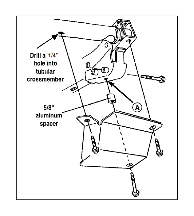
Steering box skid plate installation instructions
1. Remove the driver side lower bumper bolt (bolt #1) also remove lower steering box mounting bolt (bolt #2) from frame as shown in figure #1.
2. Holding the skid plate in place, placing the three holes in the skid plate over the existing holes in frame.
3. With the skid plate in place, replace the bumper bolt (bolt #1) and steering box bolt (bolt #2).
4. Use the existing hole in the frame (A) to line up the rear skid plate bolt.Put the nut inside the frame.
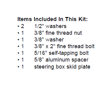
5. Put the 5/8" aluminum spacer in place, shim accordingly with supplied washers and install the 3/8" x 2" bolt (bolt #3).
6. With the skid plate in place, locate the remaining hole in the ear of the skid plate. With the hole as a guide, use a center punch to mark the location you will be drilling.
7. Drill a 1/4” hole in the frame at the location you just marked.
8. Screw the 5/16" self-tapping bolt (bolt #4)into the hole you just made and tighten.
NOTE: This Steering Box Skid Plate is compatible with oversized AGR aftermarket steering boxes.

