FREE 1 to 3-Day Delivery on Orders $149+ Details

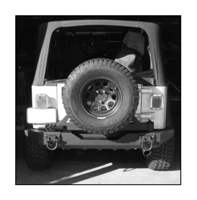
How to Install Rugged Ridge Tire Carrier for XHD Rear Bumper on your 1987-2006 Wrangler

Shop Parts in this Guide
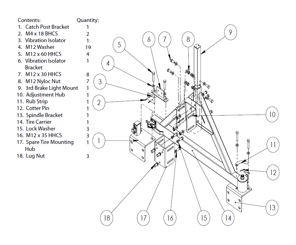
1. When installing the XHD Tire Carrier at the same time as a new XHD Rear Bumper, install sub-frames and place bumper over sub-frames. Do not install D-Rings.
If installing on an preexisting XHD Rear Bumper, remove D-Rings and loosen the subframes and side-frame brackets. This will help in lining up all of the mounting holes.
Remove spare wheel and tire from the stock or aftermarket tire carrier. Remove the stock or aftermarket tire carrier from the rear of the vehicle.
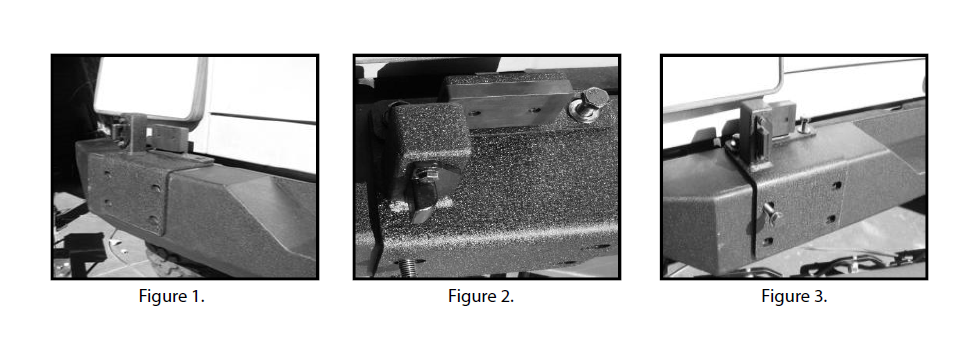
2. Place the catch post bracket and the vibration isolator assembly on the drivers’ side of the bumper and visually line up the holes (Figure 1). Insert 2 of the supplied M12 x 60 bolts and washers and place through the vibration isolation bracket, catch post bracket, and the bumper threading into the sub-frame (Figure 2). Take an M12 x 60 bolt, supplied from the XHD bumper, and thread into the top left corner face (Figure 3). Do not tighten the bolts at this time.
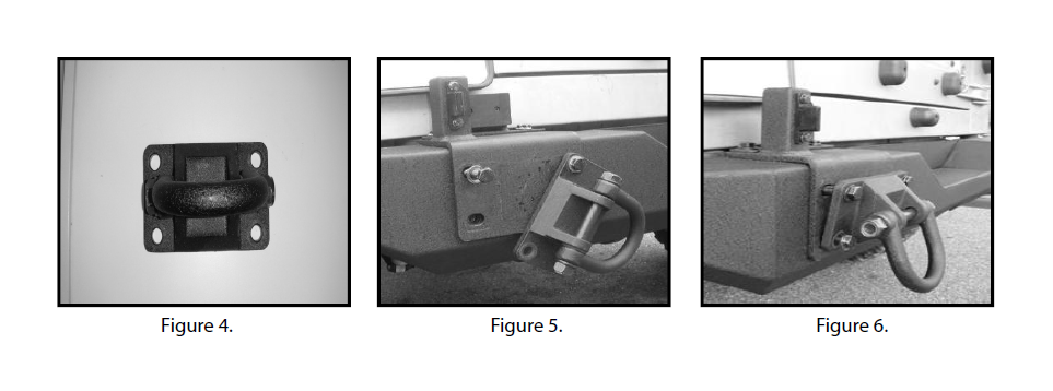
3. Attach catch post bracket to the bumper using a D-Ring. Place a D-Ring; the wider set of holes is the top of the D-Ring (Figure 4), against the catch post bracket, and insert an M12 x 60 bolt and washer through the top right corner of the D-Ring and loosely thread through (Figure 5). Remove the bolt installed in the top left corner and rotate the D-Ring into position and thread the remaining 3 bolts and washers into the D-Ring and sub-frames (Figure 6). Do not tighten bolts at this time.
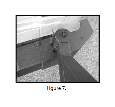
4. Place the tire carrier and spindle bracket on top of the bumper visually lining up the spindle bracket and bumper mounting holes. Thread 2 of the supplied M12 x 60 bolts and washers through the spindle bracket and bumper into the sub-frame (Figure 7). Do not tighten the bolts at this time.
5. Attach D-Ring to spindle bracket using the same procedure shown in Step 3.
6. Tighten all of the bolts for both sub-frames. If installing tire carrier on a CJ, tighten the CJ side frame brackets’ M10 x 100 bolts and nuts at this time.
Tighten lower frame mounting bolts (applicable to all vehicles)
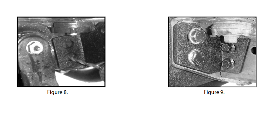
7. Mark and drill holes in the side frame rail using a 19/64” drill bit (Figure 8). Bolt the side-frame bracket into the side frame rail using 2 of the supplied self-tapping bolts (Figure 9). Repeat on the other side of the vehicle.
Note: If installing bumper on a CJ, omit this step.
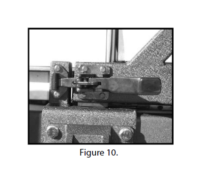
8. Adjust both the catch post bracket and spindle bracket from side to side so that the tire carrier can be latched (Figure 10).
9. Tighten the 2 top bolts on the spindle bracket.
Tighten the D-Ring bolts for both the catch post bracket and the spindle bracket.
Once the D-Ring bolts have been tightened, check to ensure that the tire carrier will still latch porperly. If the tire carrier will not latch, loosen D-Ring bolts and top bolts of spindle bracket and re-adjust as necessary.
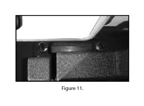
10. Once the spindle bracket and catch post bracket distances have been properly adjusted, unlatch and open the tire carrier. Slide the vibration isolator bracket forward, and tighten the top bolts of the catch post bracket. Close the tire carrier. The rubber face of the vibration isolator should be in contact with the tire carrier arm (Figure 11). If the rubber face does not contact or if the tire carrier can not be latched, adjust the vibration isolation bracket accordingly.
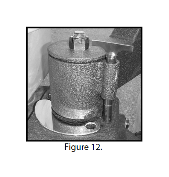
11. Open the tire carrier, and place the rub strip next to the spindle bracket. Leaving the tape on, line up the hole in the spindle bracket with the hole in the rub strip (Figure 12). Once test tted, peel o protective tape lm, and press onto spindle bracket.
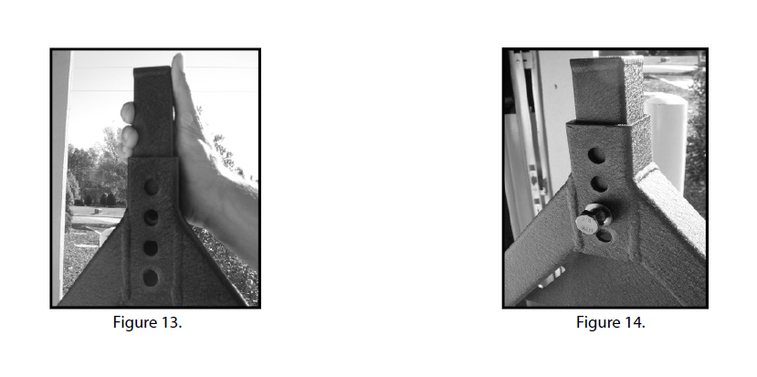
12. Place the 3rd brake light post over the opening in the top of the tire carrier and slide it in (Figure 13). With an M12 x 30 bolt and washer in hand, slide the brake post down, and insert the bolt and washer through one of the adjustment holes according to desired height (Figure 14). Tighten bolt.
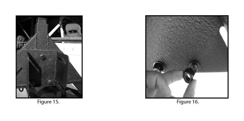
13. Open the tire carrier and place the adjustment hub up to tire carrier A-frame and align the 3 holes. Using 3 of the supplied M12 x 30 bolts and washers, insert through the tire carrier and the adjustment hub (Figure 15). Using 3 more washers and 3 nyloc nuts, place the washers over the bolt and thread the nyloc nuts onto the bolts (Figure 16). Tighten using a 3/4” wrench and 18mm socket and ratchet.
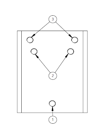
The tire carrier hub was designed to carry both a 5 x 4.5” wheel and 5 x 5.5” wheel.
Hole 1 is the common hole for both wheel sizes. Holes 2 are for a wheel with a 5 x 4.5” bolt spacing (common to both TJ and YJ Wranglers).
Holes 3 are for a wheel with a 5 x 5.5” bolt spacing (common to CJ’s 1976-1986).
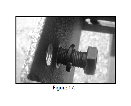
14. Once bolt spacing is selected, slide a lock washers over the supplied M12 x 35 bolts and thread the bolts (Figure 17) into the corresponding holes on the spare tire mounting hub.
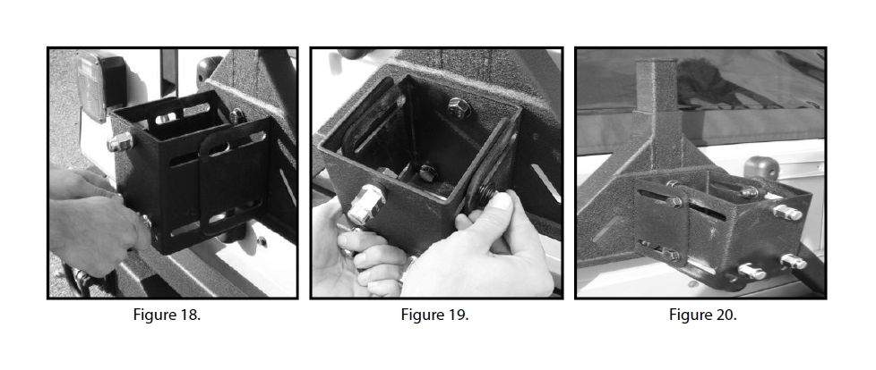
15. Slide the tire mounting hub over the adjustment hub (Figure 18). Using a supplied M12 x 30 bolt and washer, slide the bolt assembly through both the adjustment and tire mounting hubs (Figure 19). Place another washer over the bolt and thread on an M12 nyloc nut. Repeat the above steps in the other 3 slots (Figure 20). Do not tighten the nuts and bolts at this time.
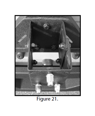
16. Pull the mounting hub all the way out. Tighten all of the tire mounting hub adjustment bolts. Do not tighten all the way down, but enough so the carrier will not move (Figure 21) with the wheel and tire mounted.
The tire carrier spindle assembly does come lightly lubricated from the factory;however, we recommend you lubricate the bearings of the spindle assembly with all purpose grease. Please refer to the model and pictures below for instruction on greasing the bearings of the tire carrier.
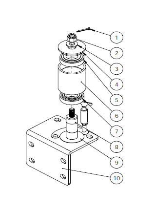
Exploded view of Spindle Assembly:
1. Cotter Pin
2. M16 Castle Nut
3. Washer
4. Upper Dust Cap
5. Upper Race and Bearing
6. Tire Carrier Spindle Housing
7. Lower Race and Bearing
8. Spindle
9. Lower Dust Cap
10. Spindle Bracket
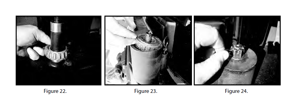
17. Disassemble the tire carrier arm from the spindle bracket. Remove the castle nut, and pry o the upper dust cap and remove the upper bearing. Remove tire carrier spindle housing and lower bearing. Leave the lower dust cap on spindle. Pack lower bearing with all purpose grease (Figure 22). Place tire carrier spindle housing over the spindle. Pack upper bearing with all purpose grease and slide over spindle into the spindle housing (Figure 23). Re-install upper dust cap, washer, thread on the M16 castle nut, and slide cotter pin through the spindle (Figure 24) and secure.
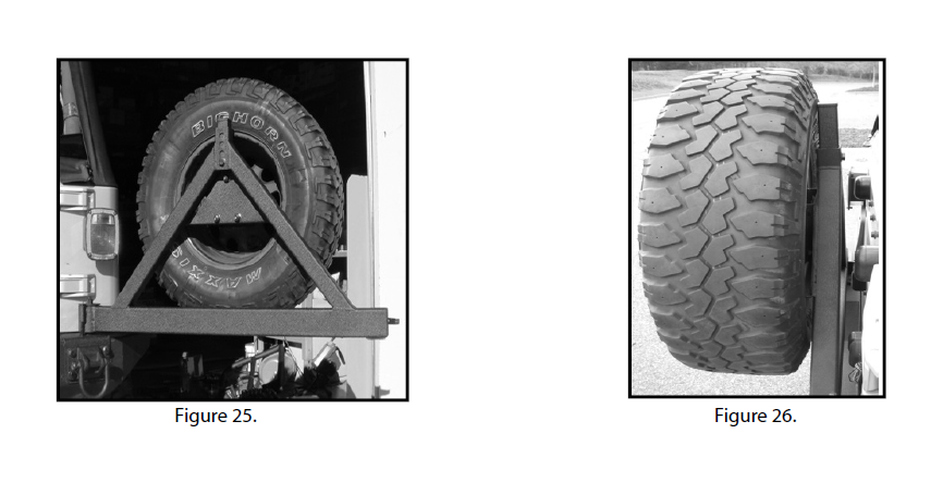
18. Slide the spare tire and wheel over the studs. Thread on and tighten the lug nuts. With the tire carrier open (Figure 25), loosen the adjustment hub nuts and bolts enough so the the tire can be easily moved. Slide the wheel and tire back towars the carrier, pull until the tire contacts the 3rd brake light post (Figure 26). Tighten all 4 of the adjustment nuts and bolts.
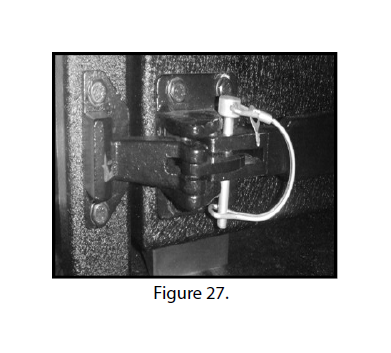
19. Close and latch the tire carrier. Insert and close lock pin (Figure 27).
This completes the installation of the 1976-2006 XHD Tire Carrier. This product is designed to be maintenance free; however, due to the nature of the product, you should periodically check the condition of the tire carrier looking for abnormal wear or damage. Discontinue use if damage has occurred, or until proper repairs are made.