FREE 1 to 3-Day Delivery on Orders $149+ Details

How to Install Rugged Ridge Mega Short Slip Yoke Eliminator Kit w/ Speed Sensor on your Wrangler

Shop Parts in this Guide
The 18676.72 kit has been designed to work with all Wranglers and XJ Cherokees with an electronic speedometer and a factory installed NP231-J transfer case. Any vehicle manufactured prior to 1992 will need to be retro fitted with an electronic speedometer (will not work with cable driven speedometers) – Not Available through OMIX-ADA or Rugged Ridge.
APPLICATION NOTES:
(1) Some early NP231 produced from 1987 – 1990 have the vacuum switch for the front axle disconnect located in the rear output shaft housing. This kit is supplied with a new housing that does not allow for the vacuum switch to be reused for this applications. It will be necessary to purchase a cable operated disconnect manufactured by 4x4 Posi-Lock or replace the front passenger side axles with later solid axle shafts.
(2) Some 1998 and older model Jeeps will have a different three wire connecter than what is supplied with this kit. If this is the case you will need to hard wire the leads to eliminate the connector all together. Wire color codes and instructions are included later in the instructions
(3) This kit will not work on 2007 and newer JK’s
(4) This kit will not work on TJ Rubicon’s or Rubicon Unlimited.
(5) Proper calibration of speedometer may be needed after installation. See chart supplied with instructions for further information.
The purpose of this kit is to replace the slip yoke portion of the NP231 with a fixed-yoke, CV-style drive shaft assembly. A CV equipped drive shaft will be required with this conversion kit. The stock drive shaft can be modified to work. Proper length and balance are critical. High –quality drive shafts in the required lengths and configurations are available to compliment this kit for many applications.
The easiest way to install this kit is to remove the transfer case from your Jeep. Removal is not necessary, but usually is much quicker and easier and highly recommended. The installation of this kit requires almost total disassembly of your transfer case. At the end of the instruction packet you will find a complete listing of replacement parts available from OMIX-ADA for your NP231J transfer case. All parts are available through the retailer this kit was purchased from.
Several suggestions that may help:
(1) The installation of this kit requires you to nearly disassemble the entire case. If you need to rebuild, or feel like you have additional worn parts, now would be the time to do so.
(2) Obtain a service manual for your Jeep. This will provide illustrations and information regarding parts identification, torque values, and other important data.
(3) Use photos, and notes; mark and label all parts for future reference.
(4) Keep all bolts, nuts, washers, ect. separated into groups as you remove them. Place inside zip-lock bags and mark location removed from.
(5) Make sure you have all the required tools, pre-lubricants, RTV sealant (OEM part number : 82300234), thread-locker, and a clean work area.
(6) Make sure you have the time needed to perform this conversion without being rushed.
STEP 1: Remove the transfer case from the Jeep. Drive shafts, speedometer drive unit, linkages, etc must be removed. The case must be separated from the transmission. Refer to your service manual for details.
STEP 2: Remove front yoke nut and yoke. Shift the range lever into the 4 Low position. Remove the selector lever. All of these parts will be re-used.
STEP 3: Remove the output shaft boot and dust shield. Some newer models may have a harmonic balancer. There may be other slight model variations. Refer to your service manual for details.
STEP 4: Remove the spacer and snap ring. Remove the seal, inner snap ring (on the shaft), and the bearing retainer ring. Remove the output housing bolts and then remove the existing output assembly.
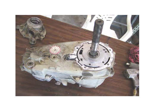
Photo 1. NP231 after completion of the first four steps of the disassembly process. The oil pump pickup tube may need to be removed before the case halves can be split.
STEP 5: Mark the locations of the rear case half bolts before removing them. Start the case separation process by using the cast-in pry bar location slots only. Prying anywhere else on the case halves may create an uneven surface that will not seal properly when reassembled. Carefully begin to pry the case halves apart. Some models will be able to remove the pickup tube and pump assembly with the rear case.
NOTE: Inspect the pickup tube o-ring and the front shaft seal in the pump. Do not take the pump apart it is not serviceable.
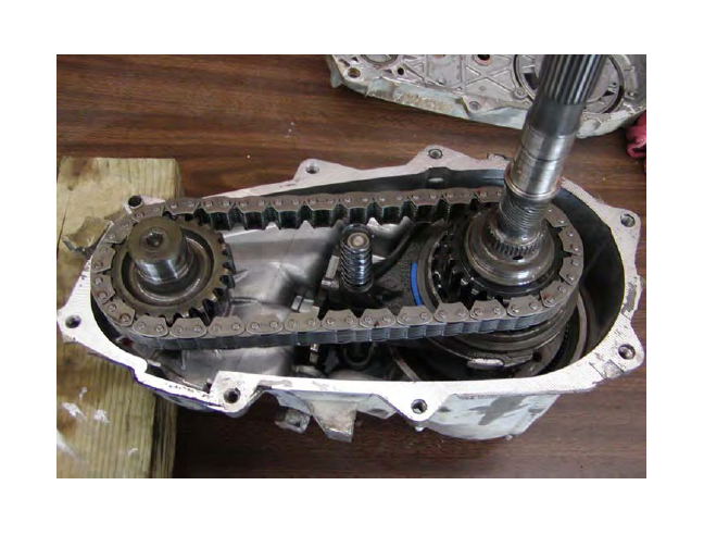
Photo 2. NP231 with the rear case and oil pump assembly removed. Clean and inspect all parts.
STEP 6: Remove the front output shaft. Remove the chain from the main shaft. Clean and inspect the chain and gears.
STEP 7: Remove the main shaft from the front case. Make note of the locations of the snap rings, mode hub and sprocket. All of these items will be positioned on the new shaft.
NOTE: On many earlier models the sprocket used two caged needle bearings. These bearings will need to be removed in order for the sprocket to be installed on the new shaft. DISCARD cage bearings – no longer needed.
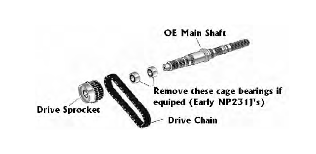
STEP 8: Be sure all parts are clean and serviceable. Prelube all parts before installation. Place the mode hub, sprocket, and retaining ring into position on the new shaft. NOTE: you may need to remove cage bearings from the drive sprocket on early NP231J. See diagram above. These bearings will not be needed – Discard.
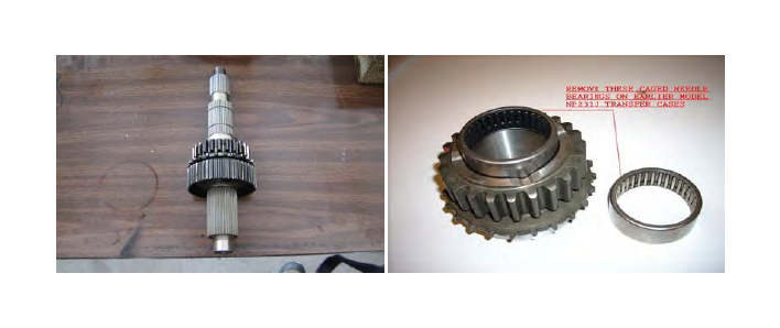
Photo 3. Mode hub, drive sprocket, and retaining ring positioned on the new main shaft.
These parts are now ready to re-install. AGAIN !! (Early model 231’s might require the removal of the needle bearing cage from the drive sprocket before it can be installed. Discard needle bearing cages as they are no longer needed.)
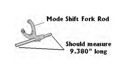
STEP 9: With the case disassembled inspect the mode fork shift rod (see image above).
If the shift rod measures 10.2” than you will need to cut it down to a length of 9.380”. This has been found to be a common problem for 1988- 1989 YJ models. You will need to cut the shift rod at the end located on the back side of the transfer case (Yoke side). Make sure that after cutting all burs and ruff edges have been cleaned.
STEP 10: Lubricate the shaft assembly, chain, and shaft bearing surfaces. Install the main shaft assembly into the front case half planetary assembly. Place the front output shaft on the chain and work them into position with the main shaft and case. Once they are properly located replace the mode spring onto the shift rail.
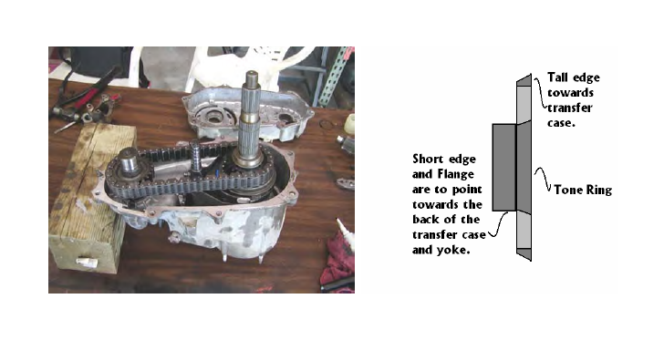
Photo 4. NP231 after completion of the first 10 steps. The rear case half is now ready to be installed.
STEP 11: Clean both halves of the transfer case and remove any excess transmission fluid. It is important to not have any oil, grease, or ATF on the case mating surfaces when ATV silicone is used.
STEP 12: Be sure the oil pump and pick up tube are properly located. Use RTV sealant ( OEM P/N: 82300234) on the case halves. A good seal will prevent oil leaks. Slide the rear case half on and into position. Do not force the case together. Rotate the oil pump as needed to engage the splines. The mode fork shift rail needs to extend through the rear case half. Before installing the case bolts start one to hold the back half of the case in place and inspect to see if oil pump pickup tube is still in the correct location. If yes than install all the bolts in their proper locations and torque to 25-30 ft/lbs. Reinstall the selector lever.
STEP 13: With the back half of the case tightened to the proper torque spec slide the speed sensor tone ring onto the main shaft (see image above). Tone ring should have the tall edge facing towards the back of the transfer case and the flanged side (short edge) should be facing the yoke (threaded) side of the main shaft.
STEP 14: Clean the mating surface of the transfer case and the Mega Short output housing before proceeding. Pre-lube bearing and apply ATV to the output housing. NOTE: the housing should already have the bearing, seal and bearing C-clip ring installed by the factory. With all components in place install the Mega Short output housing reusing the OE bolts used to hold the factory output housing in place.
WARNING!!! If you experience difficulty installing the Mega Short output housing check to make sure you have properly installed the speed sensor tone ring in accordance with step # 13. The outer edge of the sensor is sloped and must match the angle of the speed sensor pickup when installed.
STEP 15: Pre-lube the surfaces on the yokes where both the inner and outer seals will be. Slide the yokes on and tighten the retaining nuts to 170-180 ft/lbs.
STEP 16: Install the Magnetic speed sensor into the Mega Short output housing. It is important to use a small amount of oil or ATF on the o-ring to insure easy installation and avoid splitting and breaking the o-ring. Hand tighten the sensor retainer bolt and washer. Torque to 7ft-lbs. DO NOT OVER TIGHTEN, damage may occur to sensor.
STEP 17: Reinstall the transfer case into the vehicle. Be sure to reinstall the drain plug and fill it to the recommended level with the proper fluid. Reconnect all the required items like the front drive shaft, shift linkages, new 3-wire connector into factory harness.
NOTE: 4 new 5/15” – 12 point bolts have been supplied to aid with the installation of the rear drive shaft to output yoke. Do to clearance a standard ½” wrench can not be used for this application.
IMPORTANT INFORMATION!
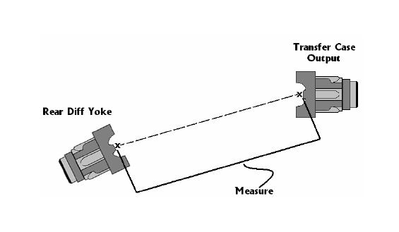
STEP 18: Proper rear CV-drive shaft measurements.
Take measurements for the required CV-equipped rear drive shaft. You will need to replace your rear drive shaft with a new unit as the original slip yoke shaft can no longer be used. Measure a straight line from the transfer case rear output yoke to the rear pinion yoke to determine the required length of your new driveshaft. If a new drive shaft is needed OMIX- ADA (Rugged Ridge) does have shafts that can be purchased depending on your vehicles overall lift. These shafts are for general use and you may want to have a custom unit made if the sizes offered will not work for your application.
Drive shaft modifications to Original Unit.
The modification of your drive shaft should be performed by a local driveline repair shop that is capable of balancing your finished assembly.
Note: Use a C.V. joint & a long slip spline style shaft assembly to avoid problems
with lifted vehicles.
If you wish to have a custom driveshaft fabricated you will need to get your new driveshaft measurement length. Use the measurement procedures listed in step #18.
Note: for proper C.V. type drive shaft operations, the rear differential yoke should be pointing at the transfer case output yoke. This should be checked under normal driving conditions and load
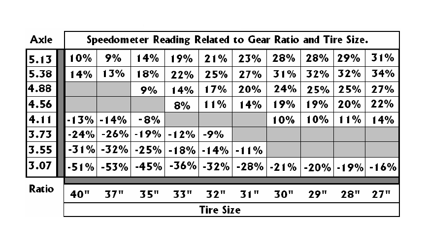
STEP 19: - Speedometer Calibration Data
Proper calibration of the speedometer will greatly depend on what changes have been made to the axle gear ratio and tire size. There are some combinations that will not require calibration changes (refer to the chart below) and are shown in the color gray.
The other data reflects what your speedometer percentage of error will be if the speedometer is not recalibrated. If your vehicle requires recalibration a converter box can be purchase. (Not Available from Omix-Ada – Rugged Ridge).
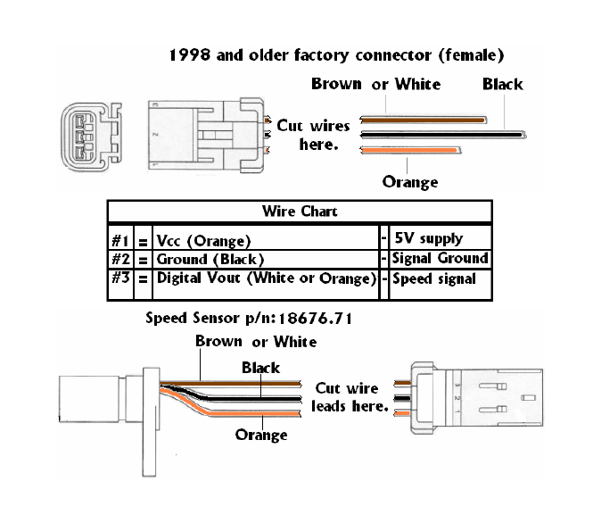
The following information will be used if working with a 1998 and older NP231J’s equipped with different connector design than what has been supplied in this kit.
For the installer to use the Rugged Ridge 18676.72 MSSYE Kit in vehicles older than 1999 it may be necessary to cut both connector leads to hard wire into the vehicles wire harness.
Wiring diagram shows the correct color code needed to splice wires.
Cut wires located directly after the female and connector located on the chasse of the vehicle and on the new 18676.71 male speed sensor supplied in the kit. This will leave you with 3 wires for both to reconnect to the new speed sensor. After trimming the plastic protective cover from both the chasses wires and the new sensor slide heat shrink wraps over each wire (cut to proper length). NOTE: the heat shrink wrap is not supplied in this kit. You will need to source this from an auto parts or electronic retailer. The Orange wire is the 5V power supply, the Black wire is the sensor ground wire, and the White or Brown wire is the sensor speed signal wire. The supplied connectors should match factory wire colors to help speed installation. With all wires properly connected (heat solder only) slide shrink tube over soldered wires and heat to seal. For added protection the use of 3M electrical tape is recommended over the shrink wrapped wires. If desired the use of connectors can be used to allow the disconnection of the sensor without removal. It is recommended that quality connectors be used to avoid corrosion at terminal connectors.