FREE 1 to 3-Day Delivery on Orders $149+ Details

How to Install Rugged Ridge Chrome LH Mirror w/ LED Turn Signal Indicators on your 07-13 Wrangler
Tools Required
- 1- Drill
- 1- 1/2" Drill Bit
- 1- 1/4" Drill Bit
- 1- Wire Crimper
- 1- 3/8" Drive Ratchet
- 1- T35 Torx Socket

Shop Parts in this Guide
- Rugged Ridge Door Mirror with LED Turn Signal; Driver Side; Chrome (07-18 Jeep Wrangler JK)
- Rugged Ridge Door Mirrors with LED Turn Signals; Black (07-18 Jeep Wrangler JK)
- Rugged Ridge Door Mirrors with LED Turn Signals; Chrome (07-18 Jeep Wrangler JK)
- Rugged Ridge Door Mirror with LED Turn Signals; Passenger Side (07-18 Jeep Wrangler JK)
Contents:
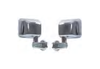
1- LH LED Mirror
1- RH LED Mirror
1- Wiring Kit
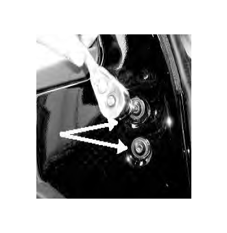
STEP 1. Remove both OE mirrors. Mirrors are held in with two torx bit screws located on the inside of the door. Retain OE hardware for use with new LED mirrors.
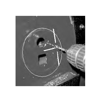
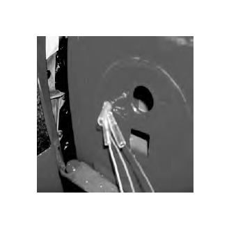
STEP 2. With the OE mirror removed, on the outside of the door, a raised circular area will be visible. With a marker, place a mark 1/2 inch inside the raised circle at the 9 o'clock position. Drill a pilot hole with a 1/4" drill bit. Make final hole with a 1/2" drill bit.
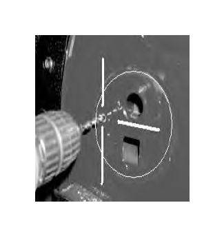
STEP 3. Repeat the same steps for marking the passenger side, with the exception of the hole will be placed at the 3 o'clock position.
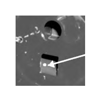
STEP 4. In the lower square hole, you will need to drill a 1/4" angled hole downward through the bottom of the internal plastic housing. This will need to be done on both doors for routing of the power wires.
STEP 5. Roll up both windows before continuing.
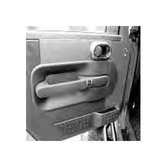
STEP 6. Remove both interior door panels. Note: Interior door panels are held in with screws and push pins. Use caution when removing the door panels as not crack the plastic panels.
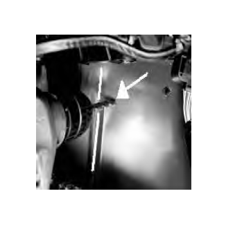
STEP 7. With a marker place a mark in the lower corner of the door towards the front inside of the jeep, approximately 4 inches up and 7" over from corner of door. Drill a pilot hole with a 1/4" drill bit. Make final hole with 1/2" drill bit. Repeat on passenger side.
STEP 8. Route the red and black wire through the hole in the outside of the door and down through the hole in the plastic housing and out through the hole on the inside of lower door section. When routing the wires do not route them inside the window channel as to cause interference with the power window.
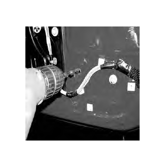
STEP 9. Thread a rubber grommet around the wires and install one on each hole drilled through the metal section of both doors. Route the wire through the factory wire loom on the door.
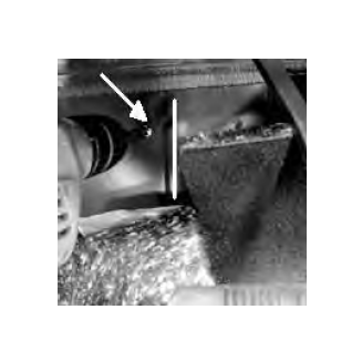
STEP 10. Pull the carpet back behind the brake pedal on the drivers side floor. Locate the raised rib on the floor pan. Drill a 1/4" pilot hole 1/2" to the left and even with the top of the rib. Finish hole with a 1/2" drill bit. Place a rubber grommet in the hole.
STEP 11. Repeat step 10 on the passenger side with the exception of 1/2" to the right of the rib.
STEP 12. Route a red wire from inside of the vehicle through the hole of the floor board to the front turn signals in the grill. This will need to be done for both side. The wheel well liners will need to be pulled down slightly to run wires.
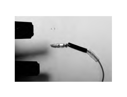
STEP 13. You will now need to terminate each end of the wires starting with the mirror heads. Install a short clear rubber boot on both the red and black wires of both mirror heads. (Note: The Yellow Wire Will Not Be Used). Cut eight 1/2" long pieces of shrink tubing. Install one piece of shrink tubing on each wire of the mirror heads. Crimp on a male bullet connector on each mirror head wire. Slide the shrink tubing over the crimped section of the wire and heat to seal the connection. Now slide the clear boot over this section. Reapeat the same procedure for the wires on the outside of the door using the longer boots with the female bullet connectors.
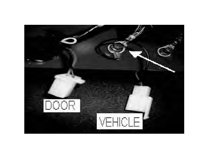
STEP 14. The wires extending out of the lower inside section of the door will receive a four pin male connector. First crimp the female brass spade connectors on the door wires. Insert the female spades into the four pin connector making sure they click in and are secure. Next crimp a blue ring terminal on a 8" piece of black wire and securing it to the grounding points located on each kick panel. Crimp on the brass male spade connectors and insert them into the female four pin connector corresponding postions as to the male four pin connector. Now plug the two, four pin connectors together insuring proper fit.
(Note: Gound Wire Must Make Good A Connection To Function Properly).
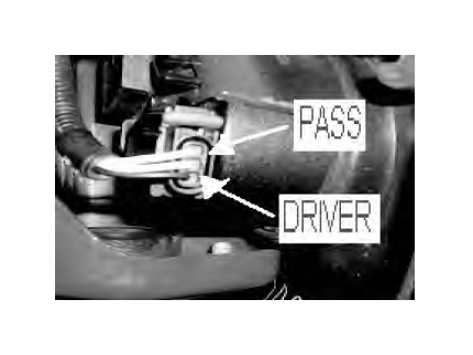
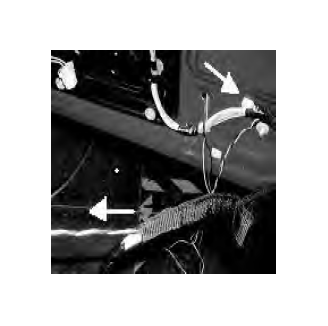
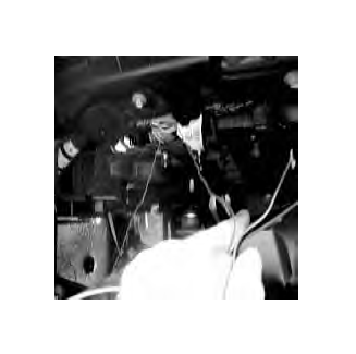
STEP 15. Locate the three pin connectors on each of the turn signals in the front grill. On the driver side turn signal the lower position wire will be used. ( White with Green stripe ) Using a blue splice connector, splice the red wire to the turn signal wire. On the passenger side the upper postion wire will be used. ( White with Brown Stripe )
STEP 16. Start vehicle and test turn signals for correct function.