 FREE 1 to 3-Day Delivery on Orders $149+ Details

How to Install a Rough Country 4 in. X-Series Long Arm Suspsension Lift Kit w/ Shocks on your 2007-2
Installation Time
6 days
Tools Required
- 10mm thru 22mm Sockets and Wrenches
- 5/8” thru 7/8” Sockets and Wrenches
- Adjustable Wrench
- Gloves
- Safety glasses
- Hand grinder
- Plasma cutter
- Resipiciating saw
- Tape measure
- 1 1/4” hole saw
- 3/8”, 17/64”, 13/32” drill bit
- Drill Motor

Shop Parts in this Guide
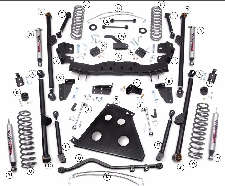
Kit Contents
· Crossmember (A)
· Crossmember brace driver (B)
· Crossmember brace passenger (C)
· Front bumpstop ext. (D)
· Rear bumpstop ext. (E)
· Driver front lower control arm (F)
· Passenger front lower control arm (G)
· Driver upper control arm (H)
· Passenger upper control arm (I)
· Front swaybar disconnects (J)
· Front brake lines (K)
· Rear brake lines (L)
· Front 2.2 shocks (M)
· Rear 2.2 shocks (N)
· Front coil spring (O)
· Rear coil spring (P)
· Adjustable front track bar (Q)
· Driver rear lower control arm (R)
· Passenger rear lower control arm (S)
· Rear upper control arms (T)
· Driver rear control arm bracket (U)
· Passenger rear control arm bracket (V)
· Rear track bar bracket (W)
· Rear sway bar links (X)
· 4-Door skid plate bracket (Y)
· Skid plate (Z)
FRONT INSTALLATION INSTRUCTIONS
1. Prior to installing this kit, with the vehicle on the ground, measure the heights of your vehicle. This measurement can be recorded from the center of the wheel straight up to the top of the inner fender lip. Record the measurements.
LF:__________ ,RF:___________, LR:__________, RR:___________
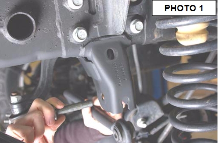
2. Place vehicle in park and chock the rear wheels. Using a 21mm socket, remove bolt securing the front track bar to the frame. Retain stock hardware. See Photo 1. Raise the front of the vehicle with a jack and secure a jack stand beneath each frame rail behind the front control arms. Ease the frame down onto the stands. Support the axle with a floor jack.
3. Remove the front tires/wheels, using a 19mm deep well socket.
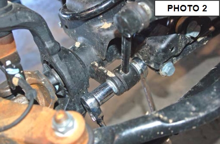
4. Using a 18mm socket and wrench remove the bottom sway bar bolts. See Photo 2.
5. Using an 18mm socket and 19mm wrench, remove the top of the sway bar link.
5. Remove the front factory skid plate with a 18mm socket.
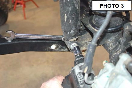
6. Remove the lower shock bolt using a 18mm socket and wrench. Using a 14mm wrench unbolt the top of the shock and remove. See Photo 3. Retain stock hardware.
7. On some models it will be necessary to remove the brake line bracket from the frame to allow the coils to be removed. Using a 10MM socket, remove the brake line bracket from the stock location.
8. Lower the axle with the floor jack to allow room for the coils to be removed. Remove stock coil springs. Retain upper coil isolators.
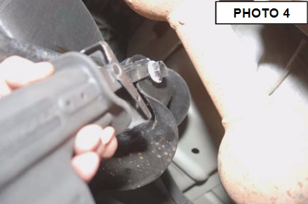
9. Remove the bolts securing the upper control arms to the axle and frame using a 18mm wrench/socket. It may be necessary to cut out the passenger side upper bolt as shown in Photo 4 to remove the control arm. A new bolt is supplied in the hardware bag to replace this factory bolt. Retain factory axle end hardware.
12. Next the upper and lower factory control arm pocket have to be removed to make clearance for the longer arms. This will be done using a plasma cutter or cut off wheel in a die grinder. Always use gloves and safety glasses.
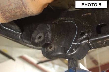
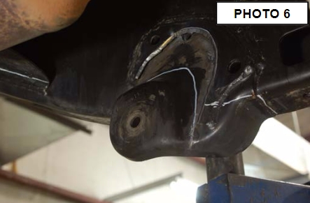
13. First cut half of the lower control arm pocket on the passenger side as shown in Photo 5. Follow around the bottom edge where the bracket tapers down to the frame. Be careful not to cut through the frame. In Photo 6 you can see where the first cut is made.
14. Next cut the other half of the control arm pocket as shown in Photo 6. Follow around the bottom edge where the bracket tapers down to the frame, then cut the bottom side of the bracket flush with the bottom of the frame.
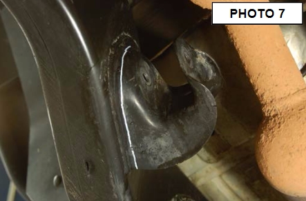
15. Finally cut the upper control arm pocket as shown in Photo 7. Follow around the bottom edge where the bracket tapers down to the frame.
16. Using a hand grinder clean up any sharp burrs or jagged edges left from cutting off the control arm pockets. Paint the frame with a durable spray paint to prevent rusting. See Photo 8
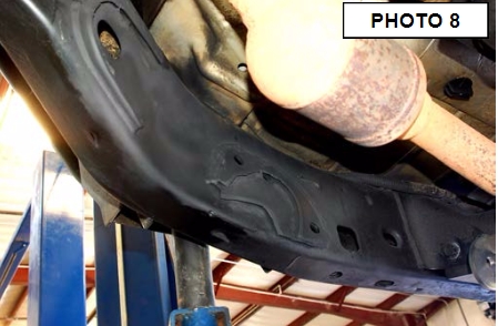
17. Repeat steps 13-16 on the driver side control arm pockets.
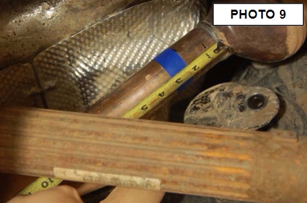
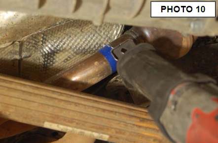
18. Steps 19 & 20 are only used if you have a 2012 or newer JK that has a 180 degree exhaust loop on the driver side.
19. Measure back 2 inches as shown in Photo 9 and mark the exhaust, next cut the exhaust pipe with a saw as shown in Photo 10. Using a 13mm wrench remove the exhaust flange bolts so the cut section of exhaust can be removed.
20. An aftermarket 180 degree exhaust pipe will have to be installed for added clearance.
21. Support the transmission with a jack stand and remove the three factory bolts from the bottom of the crossmember that holds the transmissions with a 15mm socket. Next remove the two factory bolts that connect the skid plate to the crossmember using 15mm socket. Retain factory bolts.
22. Remove four factory bolts holding the crossmember with a 18mm socket and wrench, then remove the crossmeber. Retain factory hardware.
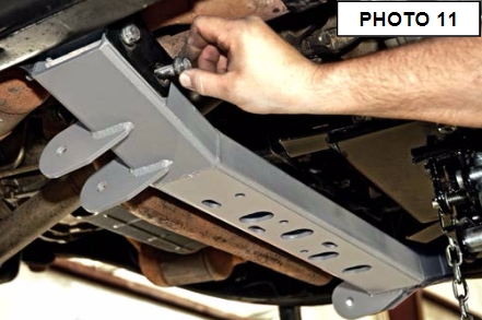
23. Next install the supplied new crossmember as shown in Photo 11 with the control arm pockets facing forward. Insert the four factory bolts from the back side of the crossmember with the thread side forward. Do not tighten at this time.
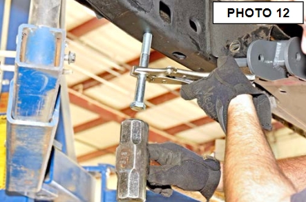
24. Using a transfer punch or a old bolt knock the factory thread insert out of the frame where the factory skid plate bolted to the bottom side of the passenger side frame rail. See Photo 12
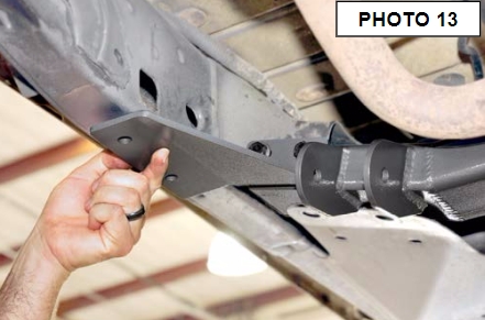
25. Slide the passenger side crossmember support bracket over the factory crossmember bolts as shown in Photo 13. Hand tighten with the factory nuts.
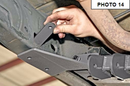
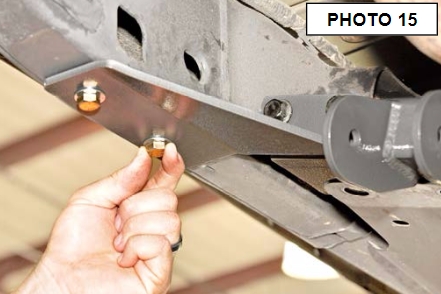
26. Next insert the crossmember brace threaded tab through the frame hole in Photo 14. Align the holes in the tab and bracket, using the supplied 7/16” x 1.5” long bolts, washers, and lock washers out of 1787bag1. See Photo 15 Tighten with a 5/8” socket.
27. Finally tighten the crossmember bolts with a 18mm socket and wrench. Make sure the crossmember is centered between the frame before tightening the bolts.
28. Repeat steps 24-27 on the driver side.
29. Remove the jack stand holding the transmission and let the transmission studs drop into the crossmember. Using a 15mm socket insert and tighten the three nuts holding the transmission to the crossmember.
30. Insert two of the crossmember flag nuts into the slotted holes in the crossmember and align the flag nuts with the two factory holes in the skid plate. Tighten factory bolts with a 15mm socket.
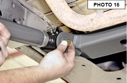
31. Adjust the supplied front lower control arms to the length of 34 3/4” center to center. Install the flex joint end of the lower control arm to the crossmember using the supplied 9/16” x 4” long bolts, nuts, and washers from 1787bag3. See Photo 16. Tighten with a 21mm socket and a 22mm wrench. Use a adjustable wrench to tighten the jam nut.
32. Insert the rubber bushing end of the lower control arm to the factory axle mount, use factory hardware and tighten with a 21mm socket and wrench.
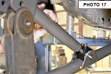
33. Adjust the supplied upper control arm to the lenth of 17 1/4” center to center. Install the flex joint end of the upper control arm to the bracket on the lower control arm using the supplied 10mm x 80mm long bolts, washers, and nuts. Tighten with a 5/8 socket and a 11/16 wrench. See Photo 17.
34. Install the bracket end of the upper control arm to the factory axle mount using factory hardware. Tighten using a 18mm socket and wrench.
35. Repeat steps 31-34 on the driver side.
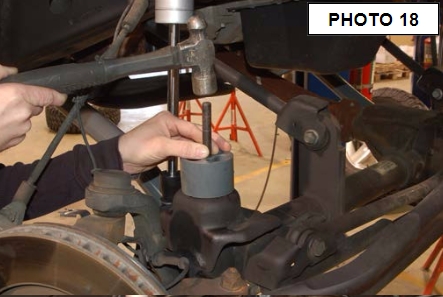
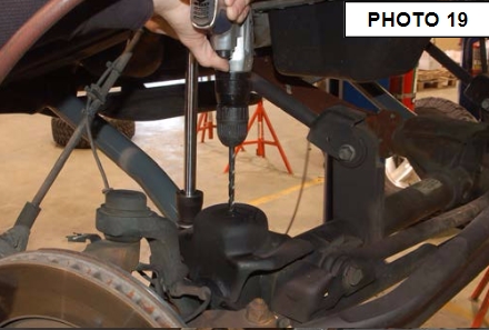
36. Place the supplied 2” bump stop in place on the lower coil seat as shown in Photo 18. Mark & drill using a 3/8” drill bit. See Photo 19.
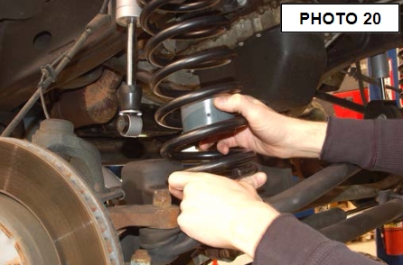
37. Be sure the factory rubber isolators are in place and install the front coil springs with the 2” bump stop pucks as shown in Photo 20. Insert the coil into the upper tower first, followed by the lower seat.
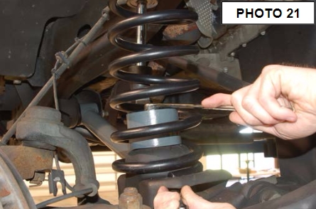
38. Secure the bump stop to the drilled hole in the lower seat using the supplied 3/8” x 3” bolts, washers and nuts. Tighten using a 9/16” wrench. See Photo 21.
39. Install the shock absorber # 660585. Assemble the cup washer and stem bushing on the stem end of the shock and insert in the upper shock tower. Tighten using a 9/16” wrench. Insert lower mount to axle using factory hardware.
40. Loosen the stock brake line from the metal line on the frame rail shown using a 12 mm line wrench. A catch pan will be needed to catch the brake fluid.
41. Remove the line from the frame rail using a 10mm socket. Next remove the brake line from the caliper and replace the brake line with the supplied stainless steel lines and brackets. Reattach at the caliper using supplied crush washers, tighten line and install the spring clip. After the install is complete the brae lines will have to be bleed.
42. For the front sway disconnects, assemble the supplied jam nut and end link on the sway bar link body. Adjust the sway bar to approx 11” for a 4” & 6” kit measuring end to end. Tighten the end and jam nut using a 18mm wrench.
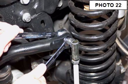
43. Install the new sway bar link on the factory sway bar as shown in Photo 22 with the supplied 12mm Flange lock nut using a 16mm & 18mm wrench.
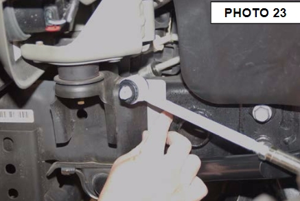
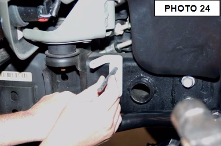
44. Install the new sway bar link on the sway bar bracket and swing up the assembly to the frame rail. See Photo 23. Remove the sway bar link from the bracket while holding the bracket in place.
45. Mark the holes to be drilled and remove the bracket from the frame. See Photo 24.
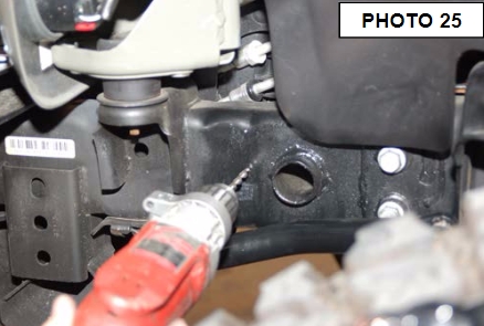
46. Drill the two holes per side using a 17/64” drill bit. See Photo 25. Be sure to only drill through outside of the frame.
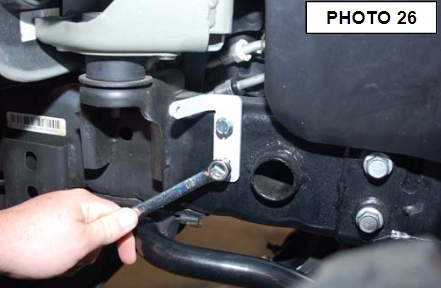
47. Install the frame bracket with the supplied 5/16” self tapping bolts (2 per bracket) using a 1/2” wrench. Photo 26.
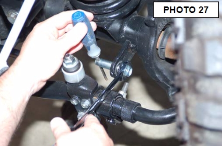
48. Install the supplied mounting pin on the axle as shown in Photo 27. Use a punch or screw driver to hold the pin and tighten using 19mm socket / wrench.
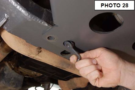
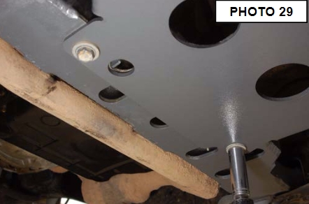
56. Using two of the crossmember flag nuts and factory skid plate bolts attach the skid plate to the crossmember as shown in Photo 28 & 29. Tighten with a 19mm socket.
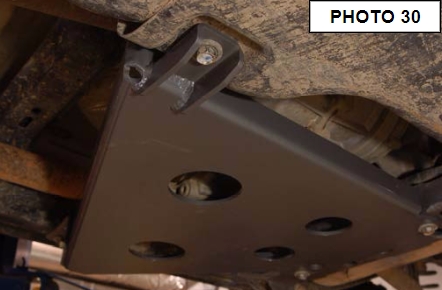
57. Use stock hardware and a 19mm socket to bolt the skid plate to the gas tank mount. See Photo 30
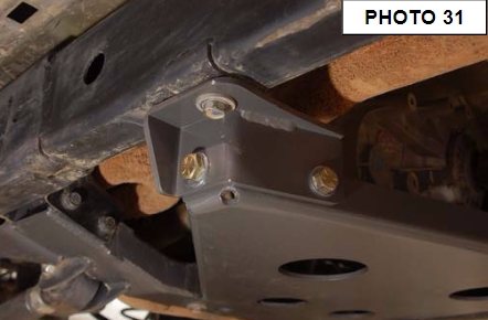
58. Next if you are installing on a 4-door use the skid plate mount as shown in Photo 31. Use the supplied 9/16” x 1 1/2” bolt, washers, and nut and the supplied 1/2” x 1 1/2” long bolt, washers, and nut to bolt the mount to the skid plate. Tighten the 9/16” bolt with a 21mm socket and 22mm wrench and tighten the 1/2” bolt with a 19mm socket. Next use factory hardware to bolt the mount to the frame. Tighten with a 18mm socket.
59. If installing on a 2-door the outside hole of the skid plate will bolt to the rear lower control arm bracket bolt.
60. Reinstall the front tires/wheels using a 19mm deep well socket.
61. Lower the vehicle to the floor and proceed to the rear installation.
REAR INSTALLATION INSTRUCTIONS
1. Chock front wheels. Jack up the rear of the vehicle and support the vehicle with jack stands, so that the rear wheels are off the ground. Position a jack so it supports, but does not raise the rear axle.
2. Remove the rear tires/wheels, using a 19mm deep well socket.
3. Using a 21mm socket and wrench remove the track bar from the frame on the passenger side. Using a 21mm socket remove the track bar bolt at the axle and remove the track bar from the vehicle. Retain the frame side stock hardware for reuse.
4. Using a 21mm socket loosen, but do not remove the bolts securing the lower control arms at both the axle and frame.
5. On the rear of the vehicle remove the factory sway bar link using a 18mm socket and wrench on the lower. Remove the upper hardware using a 18mm wrench and a 19mm wrench on the ball joint end.
6. Using a 10mm wrench, unbolt the brake hose bracket at the frame. Retain hardware for later use.
7. Remove and discard the rear shocks using a 18mm wrench. Retain stock hardware.
8. Lower the axle enough to remove the stock coil springs. Retain factory upper coil spring isolator.
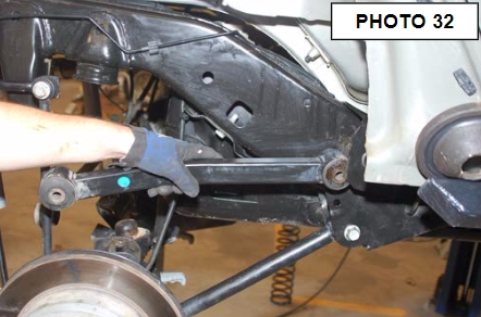
9. Remove the upper control arms from the frame and axle using a 18mm wrench. Retain the axle end factory hardware for reuse. See Photo 32
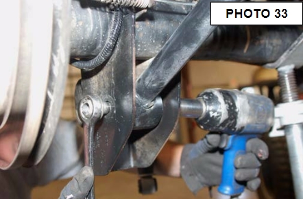
10. Using a 21mm socket remove the bolts securing the lower control arms at both the axle and frame. Passenger side lower shown in Photo 33. Remove the control arms and retain the axle end hardware for reuse.
11. Next the lower factory control arm pockets will have to be removed to make clearance for the longer arms. This will be done using a plasma cutter or cut off wheel in a die grinder. Always use gloves and safety glasses.
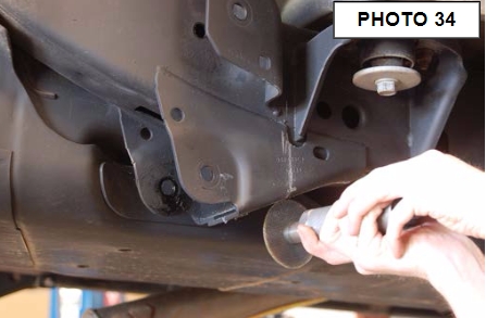
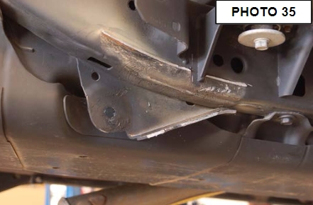
12. Starting on the passenger side control arm bracket use a cut off wheel to split the bracket into two halves. Cut along the center bottom surface. See Photo 34. Then cut the weld that connects the bracket to the outside of the frame rail. See Photo 35. Be careful not to cut into the frame rail.
13. Place a piece of cardboard or thin sheet metal between the fuel tank and inside of the frame, this will help keep sparks off the fuel tank while cutting the inside of the lower control arm pocket.
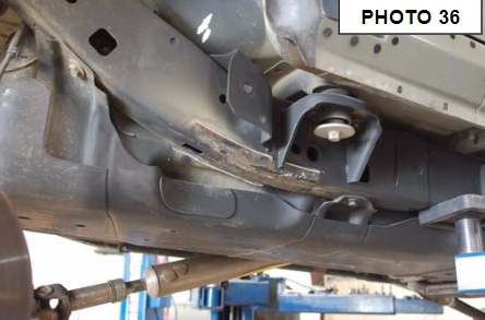
14. Follow along the bottom side of the frame cutting through the control arm pocket. See Photo 36.
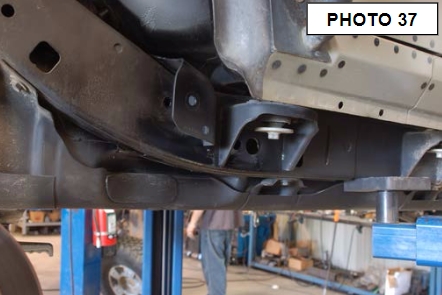
15. Using a hand grinder clean up any sharp burrs or jagged edges left from cutting off the control arm pocket. Paint the frame with a durable spray paint to prevent rusting. See Photo 37.
16. Repeat steps 12, 14, and 15 on the driver side control arm pocket.
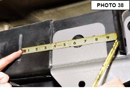
17. Slide the passenger rear control arm mounting bracket onto the frame and measure 3 5/8” from the slot in the frame to the edge of the supplied bracket. Use a block of wood and a jack to hold the bracket to the frame while drilling. See Photo 38
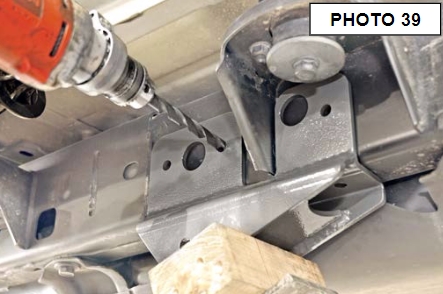
18. Using the control arm bracket as a drill pattern and drill six holes in the frame with a 15/32” drill bit as shown in Photo 39.
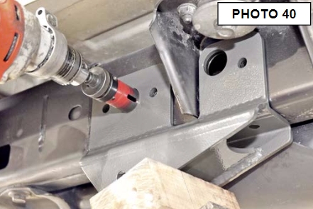
19. Using a 1 1/4” hole saw and the bracket as a template, cut two holes for flag nut access as shown in Photo 40.
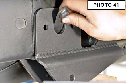
20. Insert the threaded tab through the back 1 1/4” hole as shown in Photo 41 and push the tab forward until it aligns with the front and middle hole on the bottom of the control arm bracket.
21. Using the 7/16” x 1.5” bolts, washers, and lock washers out of 1787bag4 start two of the bolts into the threaded tab.
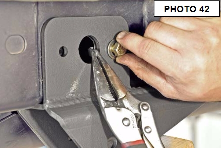
22. Using three of the short flag nuts out of 1787box4, insert the flag nut through the 1 1/4” holes and hand tighten the 7/16” x 1.5” long bolt, washer, and lock washer. See Photo 42
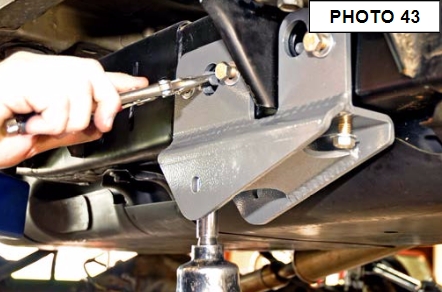
23. Next using the longer flag nut out of 1787box4, insert the flag nut through the back 1 1/4” hole and align the nut with the bottom rear hole in the control arm bracket as shown in Photo 43. Insert the 7/16” x 1.5” long bolt, washer, and lock washer and tighten with a 5/8 socket. Make sure when you tighten the bolts for the flag nuts you are holding the stem of the flag nut with vise grips.
24. Locate the supplied passenger rear lower control arms from box 1787box4 and adjust the length to 41 1/8” center to center of each end.
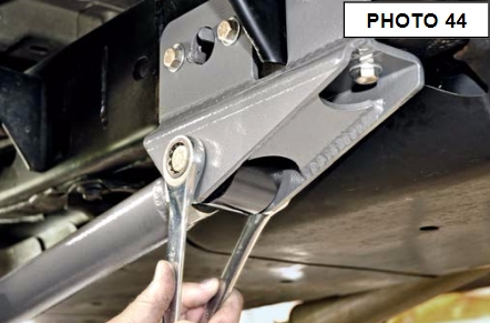
25. Insert the flex joint end of the control arm into the new frame bracket using the supplied 9/16” x 4” long bolt, washer, and lock nut from bag 1787bag3. Tighten with a 21mm and 22 mm wrench shown in Photo 44
26. Insert the rubber bushing end of the control arm into the axle mount, using stock hardware and tighten with a 21mm.
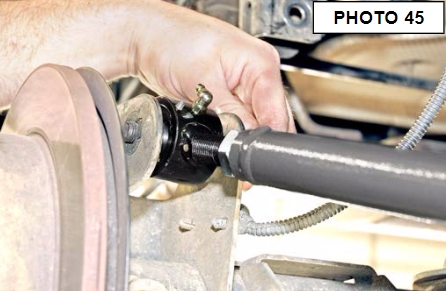
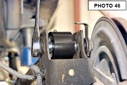
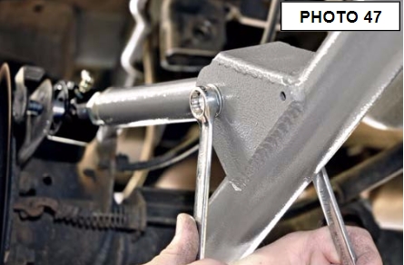
27. Adjust the upper control arm to length to 12 1/4” and insert the rubber bushing end to the bracket on the lower control arm using the 10mm x 80mm long bolt, washer, and locknut. Hand tighten.
28. Next insert the flex joint end of the upper control arm into the factory axle bracket using stock hardware as shown in Photo 45. Tighten with a 21mm wrench as shown in Photo 46. Now tighten the rubber bushing end with a 5/8” and 11/16” wrench. See Photo 47
29. Repeat steps 17-28 on the driver side.
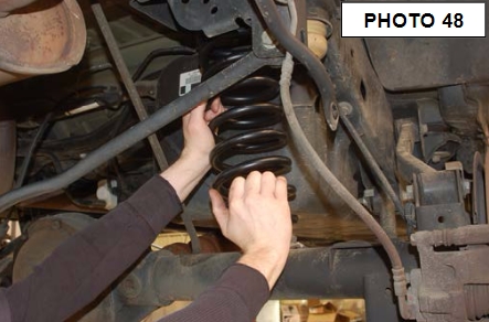
30. Install the top of the coil back onto the coil seat making sure the factory coil spring isolator is installed. When installing the bottom of the coil, make sure you install the coil spring angle correction bracket on the lower seat. This bracket helps take out any bow in the coil spring when adjusting the pinion angle. Lower vehicle slightly, watching coils to assure they properly seat on top. See Photo 48.
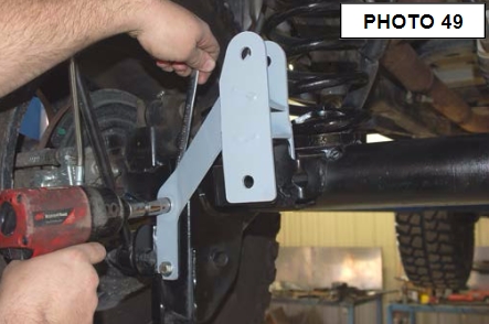
31. Position the rear track bar bracket over the rear factory track bar mount. Verify that the original track bar mounting hole and the hole in the new track bar bracket are aligned vertically. Using the track bar bracket as a template mark and drill a 13/32” hole in the top of the original track bar mount from the top.
32. Install the .375-16 x 1” bolts, washers, and nuts through track bar brace and secure with flange nut using a 9/16” wrench and socket. See Photo 49
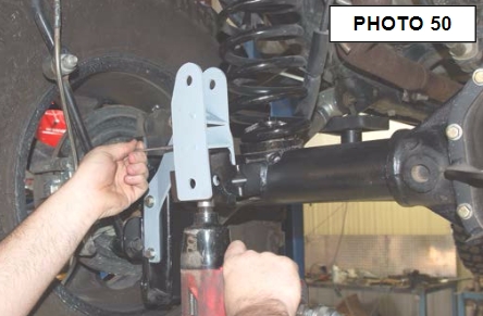
33. Install the 3/8” x 1 1/4” long bolts and flange lock nuts as shown in Photo 50 through the drilled hole. Tighten with a 9/16” socket and wrench.
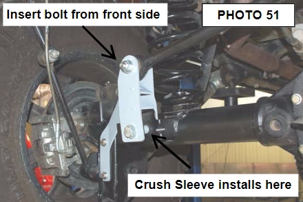
34. Insert the supplied crush sleeve, inside the factory track bar mount. Insert the supplied 14mm” x 80mm” bolt through the bracket, factory mount, and sleeve secure using the washer and nut. Tighten.
35. Install the track bar in the upper hole of the track bar bracket with the supplied 14mm x 80mm bolt washers & nut with the head of the bolt on the front by the coil spring. It may be necessary to move the axle up or down with the floor jack to align the hole with the track rod. See Photo 51
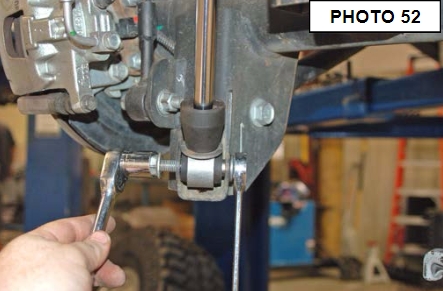
36. Locate the 4 sway bar link sleeves. Insert the sleeves into the sway bar link bushings. Using the supplied .500-16 x 2.75” bolts, washers and nuts from 1681bag3, install the sway bar links to the sway bar, and axle mount., and tighten using a 13/16” socket and 7/8” wrench. . Make sure the bolts are installed with the HEAD of the bolt toward the tire.
37. Install the rear RCX 2.2 series shocks part # 660586 using the factory hardware, using a 16mm socket for the top,
and a 18mm socket for the bottom. Shaft end of the shock will be pointed down. See Photo 52.
38. Install the rear bump stop spacers on the axle and secure with the supplied 3/8” x 3/4” bolts, washers, and nuts from 1609bag6. See Photo 53.
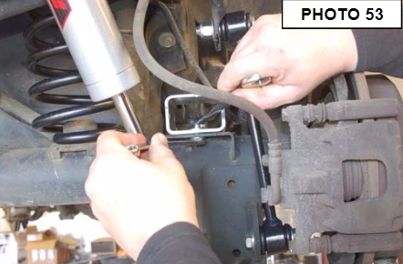
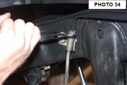
39. Remove the rubber brake line from the steel line using a 12mm wrench as shown in Photo 54 and remove the brake line from the caliper using a 15mm wrench.
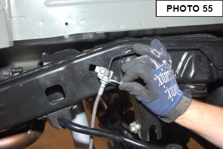
40. Install the new bracket using a 10mm wrench and stock hardware in factory location. Install the new brake line on the hard line and tighten. Install spring clip as shown in Photo 55 and secure the caliper end of the brake line with supplied crush washers, using a 15mm wrench to tighten.
41. Reinstall the rear tires/wheels, using a 19mm deep well socket.
42. Lower the vehicle to the floor.
43. Install the front track bar into the axle bracket, you may have to turn the steering wheel to move the axle left and right for the bolt hole to align.
44. Next measure from each tire to the frame making sure the front axle is centered. If needed the track bar can be removed and adjusted to the correct length to center the axle. After the adjustment all complete tighten the jam nut with a adjustable wrench.
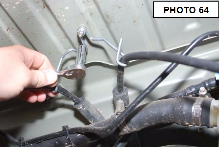
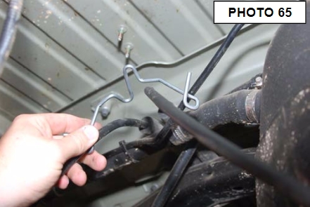
45. Remove the e-brake cable bracket from the body using a 10mm wrench as shown in Photo 64. Remove the bracket from the e-brake cable as shown in Photo 65 to allow slack in the e-brake cables.
POST INSTALLATION
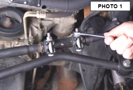
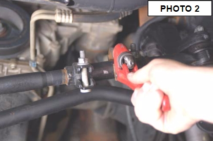
IMPORTANT NOTE : The draglink must be adjusted to the center steering wheel BEFORE the vehicle is driven. Failure to do so will cause a computer error, odd handling, and poor performance
1. Adjust front draglink to center the steering wheel before driving by loosening the two bolts and turning the adjustment collar. See Photo 1 & 2
2. Check all fasteners for proper torque. Check to ensure there is adequate clearance between all rotating, mobile, fixed and heated members. Check steering for interference and proper working order. Test brake system.
3. Perform steering sweep. The distance between the tire sidewall and the brake hose must be checked closely. Cycle the steering from full turn to full turn to check for clearance. Failure to perform inspections may result in component failure.
4. Re-torque all fasteners after 500 miles and recheck after 1000 miles. Alignment must be checked by a qualified mechanic. Visually inspect components and re-torque fasteners during routine vehicle service.
5. Readjust headlights to proper settings.
6. Have a qualified alignment center realign the front end, to the factory specifications immediately.
Caster preferred 4.6 degree range ,- 1 degree
Camber preferred –0.25 degree range ,- 0.63 degree
Toe-in preferred 0.15degree range ,- 0.15 degree
Thank you for purchasing a Rough Country Suspension System.

