 FREE 1 to 3-Day Delivery on Orders $149+ Details

How to Install Rough Country 4 In. Suspension Lift Kit on your 1987-1995 Wrangler

Shop Parts in this Guide
INSTALLATION INSTRUCTIONS
1. Raise the front of the vehicle and support with safety stands under the frame rails. Take care not to over extend the stock brake lines.
2. Remove the front wheels and tires. Remove front stock shocks. Retain the lower shock hardware for reuse.
3. Support the front axle housing with a floor jack (you must have stands under frame supporting vehicle weight).
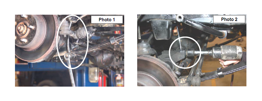
4. Remove the stock sway bar links from the sway bar and the spring pads. It may be necessary to tap the upper link on the sway bar with a hammer to release the tapered pin. See Photo 1.
5. Unbolt track bar from the axle mount on the passenger side of the front axle as shown in Photo 2 and then tie the bar up and out of the way.
6. Remove the stock brake hose bracket from the top of the frame rail by removing the one bolt located directly behind the shock towers. (Access can be gained through the engine compartment). Retain the factory torx head bolt for reuse.
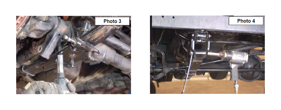
7. Remove the four front spring to axle u-bolts. See Photo 3. (The remainder of the spring removal and installation is performed one side at a time.)
8. On the driver side position a floor jack under the axle tube, just inside of the leaf spring. Raise the jack until the axle just separates from the spring. Now remove the frame bolts and the shackle bolts on the leaf spring. Retain hardware for reuse. See Photo 4. Remove the stock spring.
9. Repeat on the other side.
10. Prior to installation of new springs, thoroughly lubricate the new spring poly eye bushings and sleeves with a water resistant, lithium based grease. Loosely attach
the spring (front spring part number is 8010) to its hangers with the stock bolts, washers & nuts (unless optional spring bolt package 1184 was purchased). Note that small spring eye goes to shackle end. Snug up but do not completely tighten. Make sure spring tie bolt heads align and seat into spring perch holes.
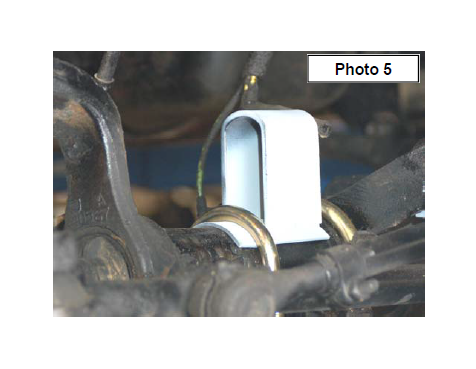
11. While installing new u-bolts, place the bump stop extension brackets on top of the axle tubes. See Photo 5. (The bump-stops are captured by the u-bolts). Tighten ubolts
to 65 ft. lbs. of torque. Tighten spring pivot bolts to 35ft. lbs. on both frame mounts and shackle mounts.
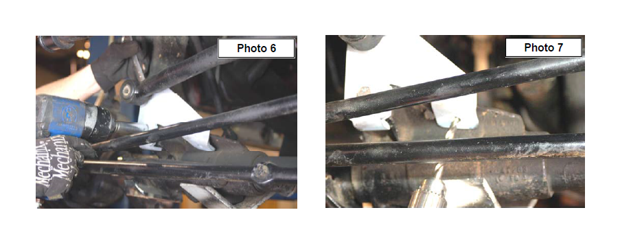
12. To install the new tracking bar bracket on the front axle housing on the passenger side, place the track bar bracket on the stock mount where the flange matches with the stock flange on the right side of the bracket as shown in Photo 6. Install supplied 12mm x 65mm long bolt and flange lock nut to secure. (Torque to 45ft/lbs). Using the hole in the new bracket as a guide, drill a 3/8" hole through the stock flange of the track bar housing as shown in Photo 7. Install the 3/8” x 1 1/4" bolt, washer and 3/8" flange lock nut. (Torque to 35 ft/lbs). Do not install the track rod to the bracket at this time.
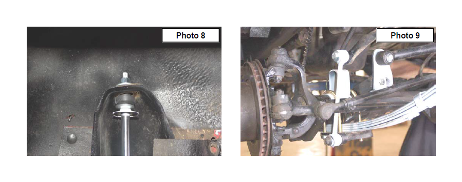
13. Assemble and install new front shock absorbers Part #658695 with the factory hardware. Tighten upper stem type mounts only until bushings swell slightly – do not over-tighten, torque lower mounts to 45 ft lbs. See Photo 8.
14. Locate the provided sleeves in 1620Bag1 bag and install into one end of the new sway bar link. Install the new sway bar link in the lower factory location on the stud with stock nut. Install on the sway bar using the supplied 12mm x 65mm bolts, washers on both sides against bushings/nuts. Tighten Hardware using a 18mm wrench See Photo 9.
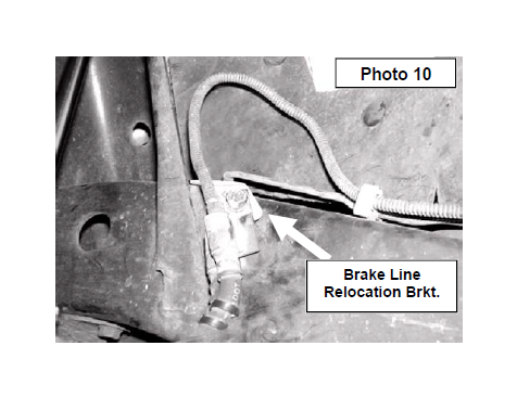
15. Install new brake line relocating brackets in stock hole reusing the T45 torx head bolt on frame rail. Pull steel line out from the frame rail (Use caution when rerouting the steel line so you do not kink the line). Mount the line to the bracket using the 5/16” x 1” bolts, washers and flange lock nut. See Photo 10.
16. Do not tighten the springs at this time. The spring hardware will be tightened once the vehicle is on the ground and the suspension has been cycled. Tightening the hardware at this time with the vehicle off the ground could
result in a stiff ride.
17. Install tires/wheels, remove jack stands and lower vehicle to floor.
18. Tighten the front spring’s shackle mount to 90-95 ft /lbs and the frame mount to 100 ft/lbs and install the track rod on the track rod bracket with the supplied 12mm x
50mm bolt, nut & washer on the head of the bolt against track rod bushing. Refer back to Photo 6.
PITMAN ARM INSTALLATION INSTRUCTIONS
1. With the tire on the ground and the full vehicle weight on the suspension, move the steering left to right, check the following for looseness, slack and wear: steering sector-to-frame attaching points, steering sector main (output) shaft, drag link and tie rod ends, track-bar mounting points and bushings.
2. With the tires off the ground, check for improper wheel bearing pre-load and ball joint wear. IT IS VERY IMPORTANT that all steering related parts are in proper working condition. If any problems exist, repair before proceeding.
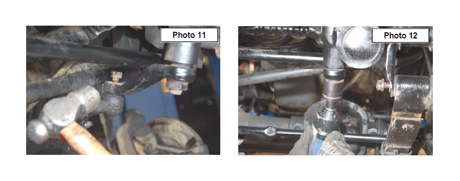
3. Remove the cotter pin and nut from the drag link end where it attaches to the pitman arm. Dislodge link with a tie rod end remover tool or by tapping with a hammer as shown. See Photo 11. NOTE - replace the link if any stud looseness is detected or if you can twist the stud in its socket with your fingers.
4. Using an impact remove the pitman arm nut from the steering sector output shaft. See Photo 12. Using a puller tool remove the pitman arm. Inspect the shaft splines for excessive wear, repair if needed. Retain hardware for reuse.
5. The arm and shaft splines should be clean and free of grit. Install new arm, factory lock washer and nut; torque to 170-230 Ft. Lbs.
6. Attach the cleaned drag link stud to the pitman arm. Torque slotted nut to factory specifications and install suppliedcotter pin. NOTE - If the drag link end stud is tightened in a position other than the straight ahead position or allowed to twist in the adjustment collar, vehicle drift to the left or right could occur.
7. Check for over extension (stud bind) as follows: To achieve the greatest possible linkage angle, have the truck frame resting on jack stands with the front axle hanging at full extension travel. Check drag link ends, with the steering wheel turned full lock in both directions; to be sure studs still have the some pivot capability.
8. Check for adequate linkage clearances while turning steering wheel lock to lock. Re-torque all fasteners and double check cotter pins.
9. Have toe-in adjustment set to factory specs.
REAR INSTALLATION INSTRUCTIONS
1. Chock the front tires and jack up the vehicle. Place safety jack stands under rear frame rails.
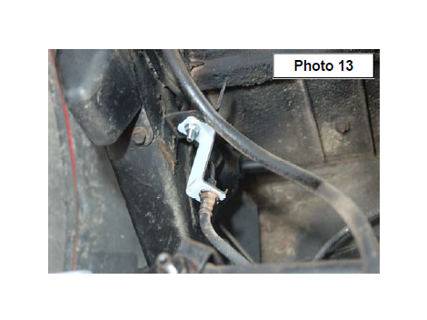
2. Remove the retainer clip that attaches the stock rubber brake hose to its upper mount bracket. This is where the rubber hose ends and the metal line starts on the driver side frame rail. Insert the new “Z” bracket in between the stock mounting bracket and the hose end. The 5/16” x 1”
bolt and flanged lock nut are used at the bracket to bracket end. Position the hose/line through the slot and into the hole on the “Z” bracket’s opposite end and then reinstall clip. See Photo 13.
3. Remove the stock u-bolts from the axle using a 3/4” socket
4. With the axle at full droop. Position a floor jack under the axle for support and remove the leaf spring hardware securing the springs to the frame and shackles. Retain the hardware for reuse.
5. Remove the rear springs from the frame mount and the shackles.
6. Disconnect rear track bar from the axle on the driver side of the vehicle using a T55 torx head bit. Retain the hardware for reuse.
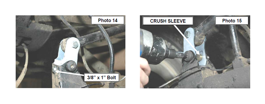
7. Install new track bar relocation mounting bracket on the axle by placing it into the factory mounting point and installing 3/8” x 1.00” long bolt, flange lock nut and washer into the hole as shown. Use factory hardware & supplied crush sleeve in stock mounting location. Install the supplied 12mm x 65mm long bolt and flange lock nut in the upper hole to secure the track rod to the new bracket. See Photo 14 & 15. Do not tighten at this time.
8. Prior to installation of new springs, thoroughly lubricate the new spring poly eye bushings and sleeves with a water resistant lithium based grease. Install with the stock bolts in the stock location (unless optional bolt package 1184 was purchased).
9. Install new springs with shims. (torque u-bolts 65 ft. lbs.) The bump-stop extension bracket will install under the ubolts as on the front. When installing the springs the thick part of shim goes toward front of jeep. Do not fully tighten the springs and the track bar to factory specs until the vehicle is on the ground. Tightening beforet he weight is on the vehicle may prevent the shackles from moving to their natural position and result in the arched spring being pinned forward against the frame.
10. Install shocks Part # 658700 with the factory hardware. Torque upper and lower mounts to 45-ft. lbs.
11. With the addition of shackles or any other extra lifting device there may not be adequate clearance between the shock body and the axle tube. In this situation your only option is to relocate the lower shock bracket to gain clearance on the axle tube.
12. Install tires / wheels.
13. Remove jack stands and lower vehicle to floor. Tighten the shackle bolts to 90-95 ft. lbs. and the frame end bolts to 100ftlbs. Install/tighten track bar into drop down bracket with the factory hardware and tighten to factory specs..
TRANSFER CASE INSTALLATION INSTRUCTIONS
1. Place floor jack under transmission mount skid plate. Make sure the jack is centered.
2. Using a floor jack, support the skid plate.
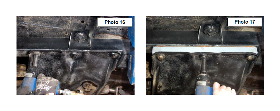
3. Slightly loosen the bolts on the transfer case skid plate on both sides to allow for some movement. Do not remove the bolts. See Photo 16.
4. Proceed to either side. NOTE: Do not attempt to take out the bolts on both sides simultaneously. Installation is done one side at a time. Remove the three bolts holding the transfer case skid plate to the frame rail. Note: It may be necessary to loosen the bolts holding the transfer case to the skid plate to allow for movement to install the lowering spacers on the skid plate.
5. Locate transfer case cap plug bag and install in the transfer case spacer. Slightly lower the skid plate and insert the transfer case lowering spacer. See Photo 17. The spacer has a front and back (the holes line up in only one direction). When the transfer case is dropped it will tend to move forward, to get the new bolts to align with holes in frame rail you will probably have to push the transfer case skid plate towards the back of the vehicle or loosen the transmission mount bolts on the bottom of the skid plate.
6. Using the conical bolts supplied slightly tighten the bolts. Do not fully tighten to allow for some movement for the opposite side.
7. Proceed to the opposite side of the vehicle and install the brackets as instructed above. After installing both sides, tighten bolts– do not over tighten.
8. It may be necessary to remove some material from the body underneath the shifter on the manual shift models to allow clearance for shifting into all gears. To accomplish this, remove the shifter boot from the shifter. Go through the shift pattern and note where the shifter is coming in contact with the body. Remove approximately ¼”- of material from the body with a small grinder. Generally the gears affected are 2nd, 4th and reverse. Go through the shift pattern again and note any contact. Trim accordingly. Reinstall the boot and secure.
POST INSTALLATION INSTRUCTIONS
1. Check all fasteners for proper torque. Check to ensure there is adequate clearance between all rotating, mobile, fixed and heated members. Check steering gear for interference and proper working order. Test brakes.
2. Perform steering sweep. Check to ensure brake hoses have sufficient slack and will not contact rotating, mobile, or fixed members, adjust lines/brackets to eliminate interference and maintain proper working order. Failure to perform inspections may result in component failure.
3. If larger tires (10% or larger than stock) are installed, speedometer recalibration is necessary.
4. Bump stops and extensions must be in place on all vehicles! Note: allowing suspension to over extend by neglecting to install or maintain stops and extensions may cause serious damage to related components.
5. Using an certified alignment professional with experience in aligning lifted vehicles, get an alignment done to factory specifications.
6. Readjust headlights to proper settings.
MAINTENANCE INFORMATION
It is the buyers ultimate responsibility to have all bolts/nuts checked for tightness after the first 100 miles and then every 1000 miles. A qualified professional mechanic must inspect wheel alignment steering system, suspension and driveline systems at least every 3000 miles.
