 FREE 1 to 3-Day Delivery on Orders $149+ Details

How to Install Rough Country 2 In. Body Lift Kit on your 1987-1995 Wrangler
Tools Required
- Floor Jack
- Jack Stands
- Wood Blocks
- 3/8" Socket / Wrench
- 7/16" Socket / Wrench
- 1/2" Socket / Wrench
- 5/8" Socket / Wrench
- 3/4" Socket / Wrench
- Drill Motor
- 1/4" Drill Bit
- 11/32" Drill Bit
- Hammer
- Penetrating Oil
- Phillips Screwdriver
- Flat Screwdriver
- 7mm Socke

Shop Parts in this Guide
INSTALLATION INSTRUCTIONS
1. Disconnect the negative battery cable using 1/2 wrench.
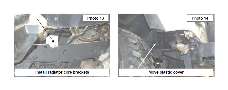
2. Remove plastic jeep cover from front of vehicle using 3/8 wrench and metal plate that also hold brake line.
3. Disconnect air intake from air filter housing and from throttle body. Depending on year remove power steering reservoir from fan shroud. Use a 13mm wrench.
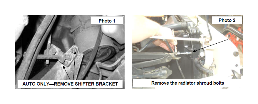
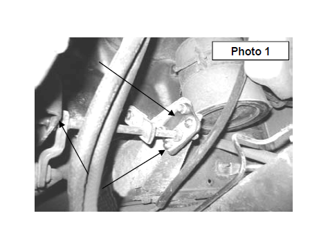
4. (AUTO TRANSMISSION ONLY) Remove the linkage on the frame to allow the body to be moved up by removing the two bolts and remove the cotter pin securing it to the engine bracket. Allowing the shifter cross shaft to hang freely. Retain hardware for reuse. See Photo 1
5. Remove the 4 bolts from radiator shroud using 13mm socket. See Photo 2.
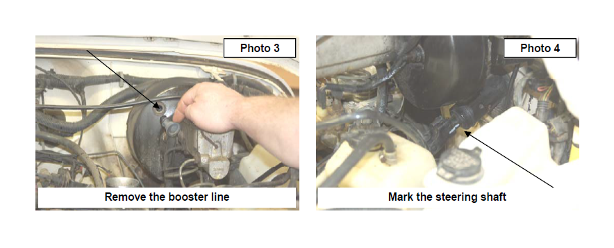
6. Unplug vacuum hose from brake booster. See Photo 3.
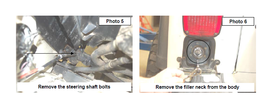
7. Mark the steering shaft and take apart using 1/2 socket on both upper and lower parts of shaft. See Photo 4 & 5.
8. Remove hard brake lines from hold down clips on frame just below master cylinder.
9. Remove gas cap and remove the bolts that attach the fuel filler hose to the plastic fuel filler bezel using a 8mm socket. See Photo 6. Be sure to push the filler hose back in the hole to avoid it hanging when jacking up the body.
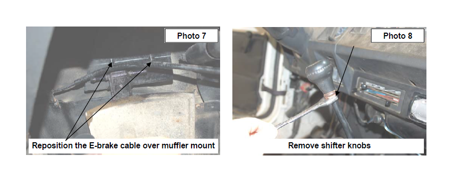
10. Move parking brake cable over exhaust hanger to allow the body to be jacked. See Photo 7.
11. Using a 3/4 wrench to loosen the lock nut securing the manual shifter shift knob on shifter and 4x4 lever. Remove both knobs. See Photo 8.
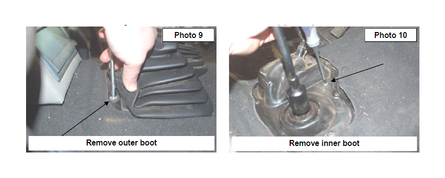
12. Remove shifter boot bolts using 8mm socket. See Photo 9.
13. Then remove screws holding in shifter bezel. See Photo 10. Pull bezel up past carpet.
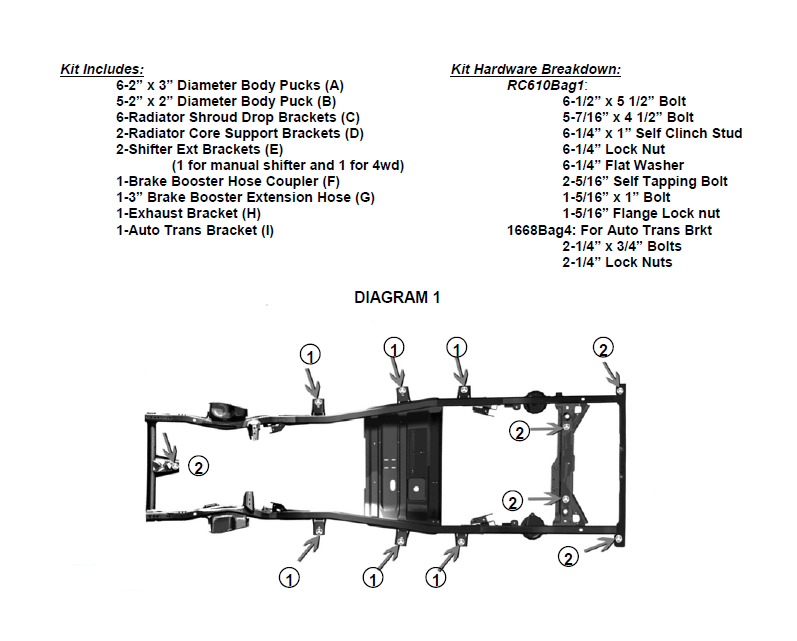
14. Loosen but do not remove the 11 body bolts. One is under center of grill, three are under doors, two above rear axle and two at each rear corner using a 5/8 socket. See Diagram 1 on Page 2.
15. Only remove bolts from one side at a time. Front center bolt must be remove for both sides. Using floor jack or jack stand and a wood block slowly raise body from frame only enough to install body puck. Watch for wires, brake lines and cables. Make sure nothing is binding. It may be necessary to unclip brake lines to allow for travel.
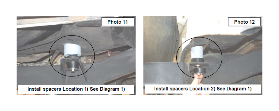
16. The 2” x 3” body puck go on the three body mounts under doors. See Diagram 1 on Page 2. Install the 3 supplied 1/2” x5 1/2” bolts. See Photo 11. Do not tighten at this time.
17. The smaller 2” x 2” body puck will go in the other 5 body mounts as shown in Diagram 1 on Page 2. See Photo 12. Install the supplied 7/16” x4 1/2” bolts. Do not tighten at this time.
18. Repeat installation of the body pucks for opposite side.
19. Install the new front bump stop extension under the bump stop on radiator core support. See Photo 13. Use the bracket as a template an mark and drill a 1/4” hole in frame. Secure using the supplied 5/16” self tapping bolt. Snug using a 13mm socket. Do not over tighten the self tapping bolt. Repeat for opposite side.
20. After all body pucks and bump stop extension are in tighten all 1/2 bolts using 19mm and 16mm for 7/16 bolts.
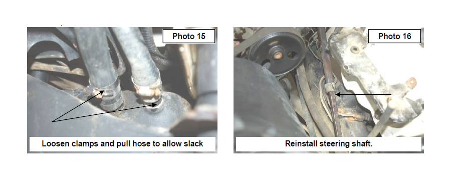
21. Remove plastic bezel under fuel filler tube and pull filler neck out. Loosen the clamps on hoses at tank using a 5/16” socket. Pull the hoses off of tank only enough to have slack in hose and be able to re-clamp. See Photo 14 & 15.
22. Test fit to make sure filler tube can be reattached to body. Tighten hose clamps and attach filler tube back to body using stock hardware and use a 8mm socket to tighten. Reinstall plastic bezel trimming maybe needed to make fit around fuel filler hose.
23. Install steering shaft with marks made earlier and use stock hardware and 1/2 socket to tighten. See Photo 16.
Note: The steering shaft may have to removed in order to free the slip joint in the shaft. After the shaft is extended, reinstall shaft.
24. Make sure vacuum lines are clear from the steering shaft. Re-position the lines if necessary.
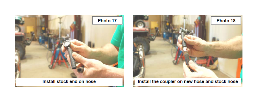
25. Remove vacuum hose end that installs in the brake booster.
26. Install the supplied rubber extension on the stock brake booster end.
27. Install the supplied coupler in the rubber extension and install the assembly on the stock line. See Photo 17.
28. Reinstall hose on the brake booster. See Photo 18.
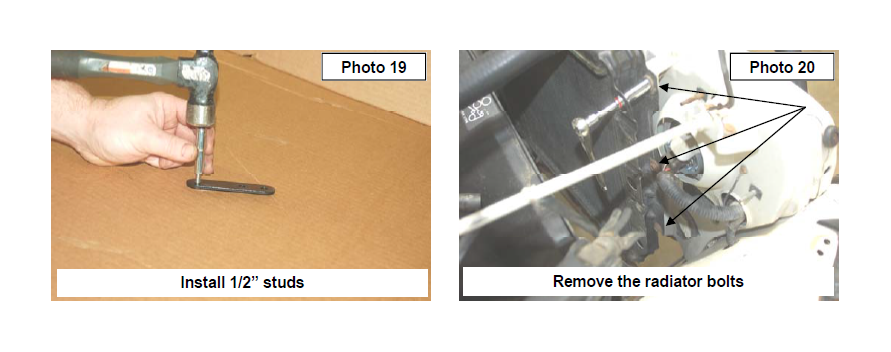
29. Install the .25” self tapping bolt into supplied radiator drop brackets using a deep well 7mm socket and hammer, by striking the bracket and pushing it on the stud. See Photo 19. Make sure stud is secured into bracket.
30. Using a 7/16 socket remove the six bolts that hold radiator on. See Photo 20. Note: Use caution when removing the radiator mounting bolts to not allow the radiator to fall and possibly damage the radiator or surrounding components.
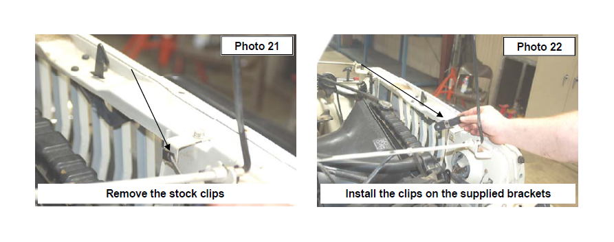
31. Remove all 6 body clip from core support and install one on each of the radiator drop brackets. The clips will install in the middle hole on the radiator brackets. See Photo 21 & 22.
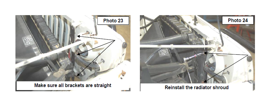
32. Install radiator support drop brackets onto core support using the supplied washer 1/4” washers and 1/4” nuts. Tighten bolts using 7/16” socket and make sure brackets are hanging straight down. See Photo 23.
33. Install radiator using stock hardware and use a 7/16” socket to tighten. See Photo 24.
34. Reinstall fan shroud and power steering reservoir using stock hardware. Use a 1/2” socket to tighten bolts. Make sure fan spins without contacting fan shroud.
35. Reinstall diff vent hose on the middle radiator mount.
36. Reinstall air filter housing if removed and battery cable. Install plastic jeep cover using stock hardware
37. Check operation of both shift levers. If there is contact with floor, slightly trim on the floor pan in the area the shifter is hitting and check operation again. Do not over-trim the area.
38. Reinstall both inner and outer shift boots checking operation while installing them. Inner boot may need to be trimmed to allow full throw of the shifter. Secure with stock hardware and use screwdriver on inner and 8mm socket on outer boot to tighten.
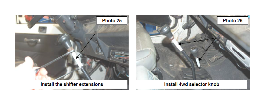
39. (For Manual Shift) Install shifter rod extension using a 7/16 wrench. See Photo 25. Install shift knobs using 3/4 wrench to set and tighten knob. See Photo 26.
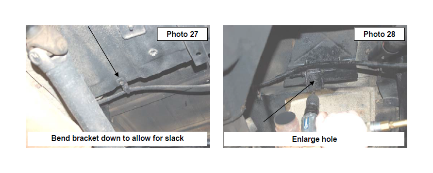
40. Bend parking brake cable bracket down located above driveshaft to allow slack. See Photo 27.
41. Remove rubber exhaust grommet from exhaust hanger.
42. Using a 3/8” socket remove bolt from exhaust hanger above muffler.
43. Enlarge the existing hole with a 11/32” drill bit. See Photo 28.
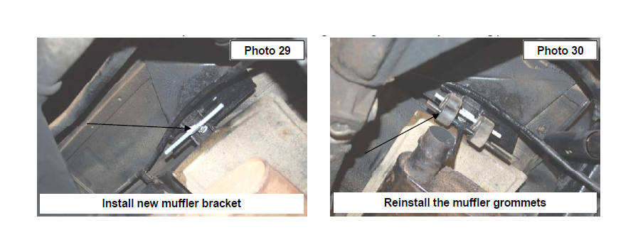
44. Install the new exhaust hanger drop bracket using the supplied 5/16” x 1” bolt and lock nut Tighten using a 13mm wrench to tighten. Install rubber exhaust grommet onto new bracket and reinstall muffler. See Photo 29 & 30.
45. (AUTO TRANSMISSION ONLY) Proceed to installation instructions for automatic shifter bracket
46. Re-Check all fasteners / components to make sure nothing is binding or in the way of moving parts.
AUTOMATIC SHIFTER BRACKET INSTALLATION
(FOR VEHICLE EQUIPPED WITH AUTOMATIC TRANSMISSION ONLY)
1. Using the supplied shifter location bracket, mount to the stock shift linkage bracket with the supplied 1/4” hardware and tighten. Note: The bolts will point toward the engine.
2. Mount the assembly in the stock location on the engine bracket and secure with stock cotter pin.
3. Mount the assembly in place on the original frame location with the stock hardware and tighten. See Photo 1.
POST INSTALLATION INSTRUCTIONS
1. Check all fasteners for proper torque. Check to ensure there is adequate clearance between all rotating, mobile, fixed and heated members. Check steering gear for interference and proper working order. Test brakes.
2. Check to ensure metal brake lines have sufficient slack to eliminate interference and maintain proper working order. Failure to perform inspections may result in component failure.
3. Readjust headlights to proper settings.
MAINTENANCE INFORMATION
It is the buyers ultimate responsibility to have all bolts/nuts checked for tightness after the first 100 miles and then every 1000 miles. A qualified professional mechanic must inspect wheel alignment steering system, suspension and driveline systems at least every 3000 miles.

