 FREE 1 to 3-Day Delivery on Orders $149+ Details

How to Install a Rough Country .75" Leveling Lift Kit on your 1997-2006 Jeep Wrangler TJ
Tools Required
- Spring Compressor
- Silicone spray
- 23/64" Drill Bit
- 17/32" Drill Bit
- 29/32" Drill Bit
- Hammer
- 13mm Socket /Wrench
- 15mm Socket / Wrench
- 18mm Socket /Wrench
- 19mm Socket /Wrench
- 21mm Socket / Wrench
- 33mm Socket
- 9/16" Wrench
- 1 1/8" Wrench
- 1 1/2" Wrench
- 1 13/16"

Shop Parts in this Guide
Thank you for choosing Rough Country for your suspension needs.
Rough Country recommends a certified technician to install this system. In addition to these instructions, professional knowledge of disassemble/reassembly procedures as well as post installation checks must be known. Attempts to install this system without this knowledge and expertise may jeopardize the operating safety of the vehicle.
Please read all the instructions before beginning the installation. Check the kit hardware against the kit contents. Be sure you have all the needed parts and understand where they go. Also please review the tools needed list and make sure you have needed tools. If you have any questions please call us at 800-222-7023.
PRODUCT USE INFORMATION
As a general rule, the taller a vehicle is the easier it will roll. We strongly recommend seat belts and shoulder harnesses should be worn at all times. Avoid situations where a side rollover may occur. Braking performance and capabilities are decreased when significantly larger/heaver tires and wheels are used. Take this into consideration while driving. Also, speedometer recalibration is necessary when larger tires are installed.
Do not add, alter, or fabricate any factory or after-market parts which increase vehicle height over the intended height of the Rough Country product purchased. Mixing component brands, lifts, and/or combining body lift with suspension lifts voids all warranties. Rough Country makes no claims regarding lifting devices and excludes any and all implied claims. We will not be responsible for any product that is altered.
The 4” suspension system was developed for 33x12.50x15 tire on an after market wheel with 3.75” of back spacing, on an 8” wide wheel. And the 6” kit was developed for a 35x12.50x15 tire. Due to the inconsistency of vehicles when manufactured and the various options available, the amount of actual lift gained by this lift kit will vary. On models outfitted with extra bolt-on equipment and accessories, Rough Country offers new coil spring isolator pads made from polyurethane to boost ride height 3/4". These are available for the front or rear. Part # 7596
With the installation of this kit and larger tires it is highly recommended that an aftermarket stabilizer be added. This kit assumes the installation of a SYE and a CV drive shaft. If a SYE and a CV driveshaft are not installed a transfer case drop and a shift control bracket will be required.
This kit features Rough Country’s adjustable joint design. Adjustable end tool is included in kit. Assemble the joints per the separate instruction sheet Part # 92RCJ120 provided.
NOTICE TO DEALER AND VEHICLE OWNER
Any vehicle equipped with any Rough Country product must have the “Warning to Driver” decal installed on the sun visor or dash. The decal is to act as a constant reminder for whoever is operating the vehicle of its unique handling characteristics. INSTALLING DEALER—It is your responsibility to install the warning decal and to forward these installation instructions on to the vehicle owner for review and to be kept in the vehicle for its service life.
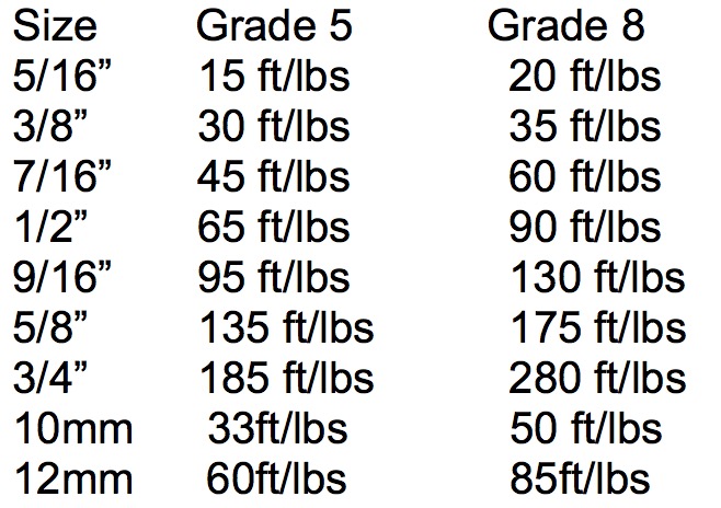
TORQUE SPECS:
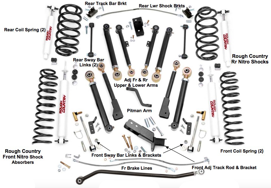
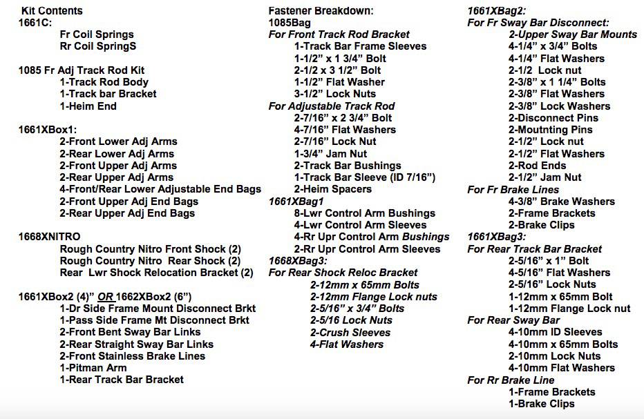
KIT CONTENTS
FRONT INSTALLATION
1. The front-end components are installed first.
2. Place the vehicle on a level surface. Set the parking brake. Center front wheels and chock rear wheels. Remove the upper stud nut, retainer and grommet from both of the front shocks using a 15mm socket.
3. Jack up the front of the vehicle and place jack stands on the frame rail behind the lower control arm mount on the frame. Installation is done one side at a time.
3. Remove the front tires and wheels.
4. Remove both of the front sway bar end links using a 18mm wrench & T55 torx bit from the axle and a 15mm for the upper stud. Place a floor jack underneath the axle for support and complete the removal of the front shock absorbers using a 13mm wrench. Retain the stock lower hardware for reuse.
5. Do not reuse the original factory shocks.
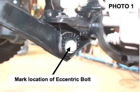
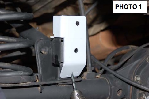
6. If your axle is equipped, mark the position of the lower control arm cam bolt and axle brackets for installation reference. See Photo 1. If equipped with ABS brakes, remove the sensor wires and clamps from the inside of the lower arms and save clamps for re-use.
7. Remove the track rod from the axle and from the frame using a 15mmwrench for the axle and a 19mm wrench for the frame.
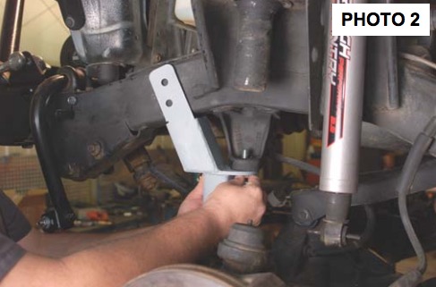
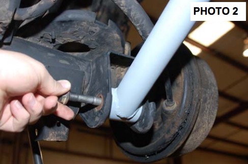
8. Install the track rod bracket as shown with the 1/2” x 1 3/4” bolt, washer & nut in the stock track rod mount. Make sure the bracket is flat against the frame. Snug but do not fully tighten at this time. Photo 2.
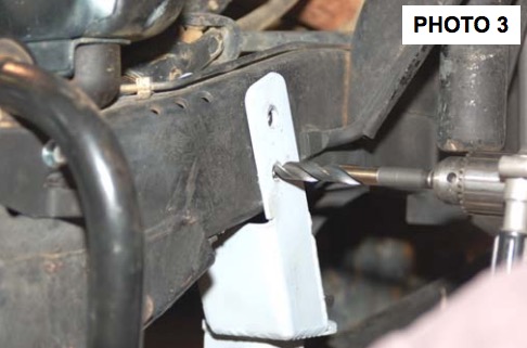
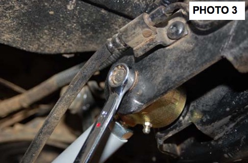
9. Using the bracket as a guide, mark and drill the two side holes through the inner and outer frame as shown in Photo 3 using a 17/32” drill bit. Make sure to keep the drill level when drilling.
10.Remove the bracket and enlarge the outside holes only using a 29/32” bit.
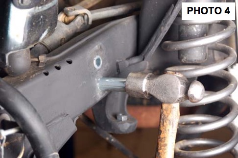
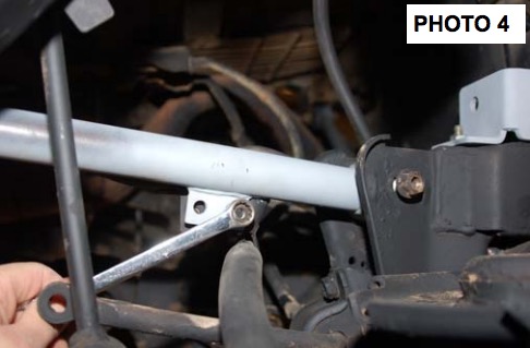
11. Install the supplied crush sleeves as shown in Photo 4 and reinstall the bracket.
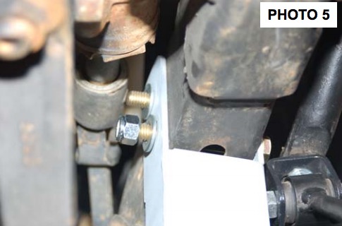
12. Secure to the frame using the supplied 1/2” x 3 1/2” bolts, washers and nuts & 1/2” x 1 3/4” bolts & nuts. Tighten the 1/2” x 1 3/4” bolts to 65ft/lbs and the 1/2” x 3 1/2’ bolts to 80ft/lbs. Tighten using a 3/4” wrench & 3/4 socket. See Photo 5.
13. Remove the coil spring clip located on the bottom coil seat on the driver side of the vehicle using a 13mm wrench. Lower the axle and remove the coil spring. A coil spring or strut compressor may be needed to remove the stock coil spring.
14. Remove the stock lower control arm by removing the nut, cam, and cam bolt (if equipped) from the axle bracket using a 21mm socket & wrench and then removing the nut and bolt from the frame bracket doing one side at a time using a 21mm socket & wrench.
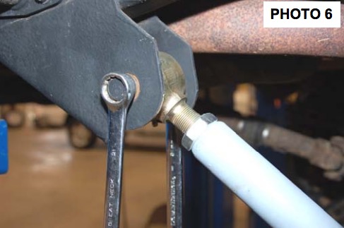
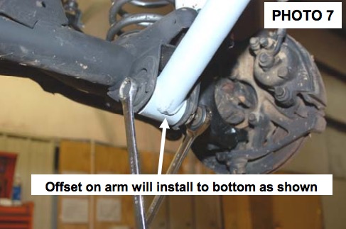
15. Lubricate control arm bushings with a lithium grease or equivalent and install in the Rough Country control arm. Adjust to 3/8” longer than the stock arm for a pre-alignment starting point. Tighten the jam nut using a 1 13/16” wrench or a large crescent wrench and install on the vehicle with the offset to the bottom using factory hardware as shown in Photo 6 & 7. Do not tighten at this time. If applicable, drill a 23/64” hole into each lower link and reinstall the ABS sensor wires. Use the original clamps.
16. Remove the stock upper control arm by removing the factory hardware from the axle & frame bracket using a 15mm wrench, doing one side at a time.
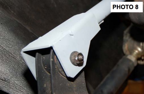
17. Adjust arm to 1/4” longer than the stock arm for a prealignment starting point. Tighten the jam nut using a 1 1/8” wrench and install on the vehicle using factory hardware – See Photo 8. Do not tighten at this time.
18. Install the coil spring. A coil spring or strut compressor will be needed for the new coil spring installation. Compress the new coil spring and install the new spring into the upper and lower spring pockets. Carefully remove the compressor and make sure the coil is seated properly in the coil seat by rotating the spring so the pig tail end fits in the spring pocket. Install the coil spring clamp using a 13mmwrench and torque to 16ft.-lbs.
19. Repeat steps on other side.
20. Remove the cotter pin and nut from the drag link at the pitman arm using a 19 wrench. Retain the nut and cotter pin to be reused. Separate the drag link ball stud from the pitman arm with a puller tool. Do not use a pickle fork.
21. Mark the position of the original pitman arm. Remove the nut and washer from the steering gear box using a 33mm socket. Align and install new pitman arm on the steering gear shaft. Install the washer, nut and tighten to 185 ft. lbs using 33mm socket.
22. Reinstall the drag link to the pitman arm using stock nut & tighten nut using a 19mm wrench. Install cotter pin.
23. Locate the front Rough Country Nitro shock absorber Part # 651997 or RCX Front Shock part #660579 and install in the factory lower mounts with the factory hardware. Install the new upper stud bushings and tighten the upper mounting point using a 9/16” wrench, slightly bulging the bushing. Do not over tighten stud bushing. Tighten the bar pin on the bottom of the shock with the stock hardware using a 13 wrench. Note: RCX 2.2 Series shock absorbers will install with the body up and the piston rod down.
24. Repeat this on the opposite side of the vehicle. Install the tires, wheels and tighten lug nuts to factory specs.
25. Lower the vehicle to the ground.
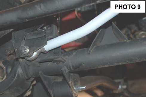
26. Install the heim end, spacers and jam nut on the track rod body and adjust to a length of 33 1/2” from end to end. Install in the factory mount on the axle with the supplied 7/16” x 2 3/4” bolt, washers & nut. Tighten using a 15mm socket / wrench. See Photo 9.
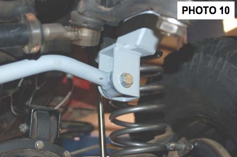
27.Swing up the track rod and install in the new track rod bracket with the supplied 7/16” x 2 3/4” bolt, washer and flange nut. Tighten to 45 ft/lbs using a 15mm wrench. See Photo 10. It is important to center the vehicle over the axle to ensure proper tracking and alignment. If needed, remove the axle end and adjust to center the body over the axle.
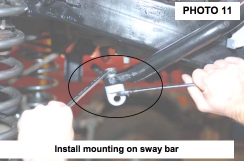
28. Install the upper sway bar mount on the top of front sway bar where the stock link was secured, using the supplied 3/8” x 1.25” bolt and washer. Tighten using a 9/16” wrench making sure the mount is straight. See Photo 11.
29. Assemble the sway bar link with the link body, the jam nut and rod end Adjust the sway bar to a length of 11 1/4” from top to bottom. Tighten the jam nut against the rod end using a 5/8” & 3/4” wrench.
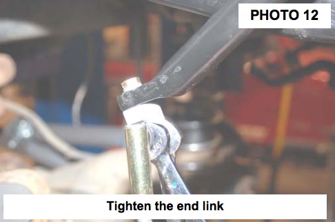
30. Install the link on the upper sway bar mount with supplied 1/2” flange lock nut as shown in Photo 12. Tighten using a 5/8” & 3/4” wrench.
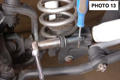
31. Install the supplied pin on the axle as shown in Photo 13 using a screwdriver as shown and a 3/4” wrench.
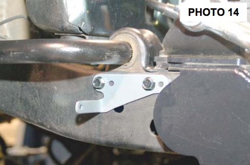
32. Remove the bolts securing the plastic shroud to the frame and install the driver and passenger side frame mount brackets in the holes shown for the 4” disconnect kit using the factory holes and the supplied 1/4” x 3/4” bolts & washers. See Photo 4. Tighten using a 7/16” wrench, be careful to not over tighten. Please note there is a passenger and driver side bracket
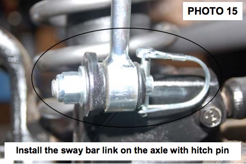
33. Swing the sway bar link down and install on the lower axle mounting pin. Install the disconnect pin & washer on the outside as shown. See Photo 15.
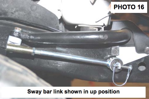
34. When disconnecting the sway bar, remove the sway bar link / washer and place it on the frame mount as shown in Photo 16 to keep the sway bar link from interfering with front end components.
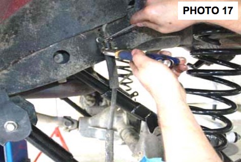
35. Remove the stock brake line from metal line at frame rail using a T40 torx bit and also on caliper. Retain stock hardware to reinstall the brake line. A catch pan is recommended to contain fluid. See Photo 17.
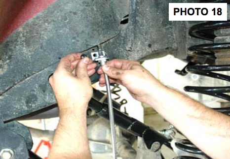
36. Install the new brake line bracket on the frame rail as shown using a T40 torx bit with supplied brake line clip. Install the new Rough Country brake line on the stock metal line and install on the caliper with stock caliper bolt and brake line washers. See Photo 18.
37. The brake system will be bled after the rear components have been installed.
38. Tighten the upper suspension arms to 65 ft. lbs using a 21mm wrench & socket (both sides).
39. Align the reference marks on the adjustment cams and lower arm axle brackets and tighten to 85 ft. lbs using a 21mm wrench & socket.
REAR INSTALLATION
1. Chock the front wheels. Jack up the rear of the vehicle and remove the tires and wheels. Place jack stands on the frame rail to support the vehicle. Place a floor jack under the differential. Remove the stock shock absorbers using a 15mm socket & 18mm wrench. Remove the sway bar links using a 15mm socket & wrench. Retain the factory shock hardware.
2. Disconnect the track bar from the axle bracket on driver side of vehicle using a T55 Torx bit and install the new track bar relocation bracket in the stock location. See Photo 1. Secure to the stock location using the factory hardware.
3. Remove the stock brake line from the driver side frame mount and axle mount. Install the new line using stock hardware on the frame and axle.
4. Carefully lower the axle with the floor jack and remove the coil springs. NOTE: It may be necessary to use a coil spring compressor to remove the stock coil springs. Be careful not to overextend the vent tube on the axle. It may be necessary to disconnect the hose during installation and reroute the hose after installation.
5. Enlarge the holes in the factory mount to accommodate the two 5/16” bolt, using the bracket holes as a guide. Install the 5/16” bolts, washers, nuts. Tighten using a 13 wrench. Do not install the track rod in the new bracket at this time.
5. Remove and replace one suspension arm at a time.
6. Remove the lower arm from the axle and frame mount using a 21mm wrench & socket. Retain hardware. 7. Lubricate control arm bushings with a lithium grease or equivalent and install in the Rough Country control arm. Adjust to 3/8” longer than the stock arm for a pre-alignment starting point. Tighten the jam nut using a 1 1/8” wrench and install on the vehicle with the offset to the bottom using factory hardware as shown in Photo 2.
8. Repeat steps on the other side.
9. Remove the rear upper stock control arms from both the frame and axle mounts using a 15mm socket & wrench. Retain the stock hardware for reuse. Remove the emergency brake line bracket from the stock control arm using a 1/2” socket. Retain hardware for reuse.
10. Lubricate bushings with a lithium grease or equivalent and install the bushings and sleeves in the upper rear control arms.
11. Adjust the control arm to a length of 3/4” longer than stock arms (1/4” if using stock drive shaft) for a prealignment starting point. Install the adjustable arms in the stock location and reuse factory hardware to install. Do not tighten at this time. See Photo 3.
12. Reinstall the emergency brake bracket onto tab on upper control arm using a 1/2” wrench. Reuse factory hardware and tighten. See Photo 4.
13. Install the new Rough Country coil springs making sure the rubber damper in positioned in the upper mount. It will be necessary to use a coil spring or strut compressor to install the new coil springs.
14. Jack up the axle to compress the coil spring and to align the track rod with the new mounting point. Install using the supplied 12mm x 65mm bolt and flange lock nut. Do not tighten at this time.
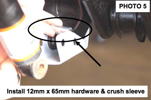
15. Install the lower shock bracket as shown in Photo 5 with the supplied 12mm x 65mm bolts, flange locknuts with supplied crush sleeves.
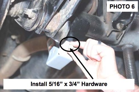
16. Install the supplied 5/16” x 3/4” bolts, washers & nuts as shown in Photo 6 in the shock bracket. Tighten the 12mm bolts using a 18mm wrench & 18mm socket. Tighten the 5/16” bolts using a 13mm socket and wrench.
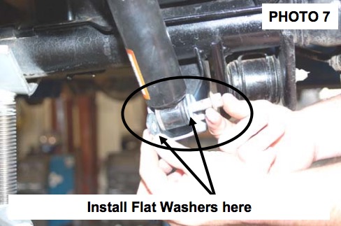
17. Install the rear Rough Country 2.2 Shock absorber Part #660576 on the upper mount and install the supplied flat washers as shown in Photo 7 on the lower shock mounts with the factory hardware. Tighten using a 15mm & 18mm wrench. (Stock shocks shown in picture). RCX 2.2 Series shock absorbers are designed to be installed with the piston down and body up.
18. Reinstall the wheels and tires. Lower the vehicle to the ground and tighten the lug nuts to the factory specifications using crossing pattern (80-110 ft. lbs).
19. On the rear, assemble the sway bar bushings and 10mm sleeves in the new rear extended sway bar links. Secure the links to the stock location, using the 10mm x 60mm bolt, washers and nuts supplied. On the upper mounts you will reuse the factory flag nut. Tighten to 40 ft. lbs using a 15mm wrench & socket.
20. Tighten lower arm pivot bolts to 130 ft. lbs using a 21mm socket & wrench
21. Tighten the rear track bar mounting bolts to 74 ft. lbs using a 18mm socket & wrench.
22. Please refer to the transfer case instructions included with that kit for transfer case drop bracket install.
23. Bleed brake system.
POST INSTALLATION
1. Bleed brake lines and test brakes before driving. Check for leaks.
2. Have a qualified alignment center realign front end to factory specs. As a general rule you set caster to the minimum of the factory spec and set toe-in to the maximum.
3. Install Warning to Driver decal on sun visor.
4. Adjust headlights to proper settings.
5. All components must be retightened after 500 miles, and every three thousand miles after installation.

