 FREE 1 to 3-Day Delivery on Orders $149+ Details

How to Install Raxiom Black Mirrors w/ LED Signal Indicators on your Wrangler

Shop Parts in this Guide
Contents:
(1) - Left LED Mirror
(1) - Right LED Mirror
(1) - Wiring Kit
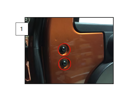
Step 1: Remove the factory mirror by removing the (2) Torx screws on the inside of the door. **Note: Factory hardware will be reused.
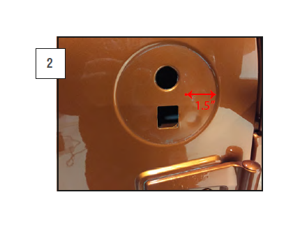
Step 2: Once the stock mirror is removed, mark 1 ½” inside the recessed mirror circle. On the Driver side at the 9 o’clock position. On the Passenger side at the 3 o’clock position. Drill a 1/8“ pilot hole, finish with a ½” hole. **Note: Paint any exposed metal. Then insert the supplied grommet. **Note: 2011 JK’s may not require this step.
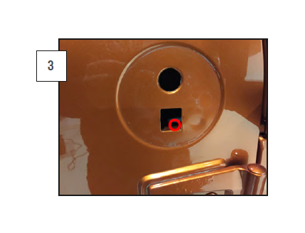
Step 3: In the lower square hole, you will need to drill a ¼” hole angled downward through the internal plastic housing. Route the mirror wires through the drilled hole. **Note: 2011 JK’s may not require this step.
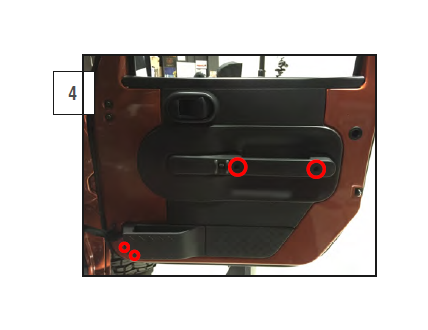
Step 4: Remove the interior door panels by removing the screws holding the panel to the door. At this point, the door panel will only be held on with the plastic push clips. Firmly pull the door panel from the door. **Note: Depending on year and model the door panels may be secured differently.
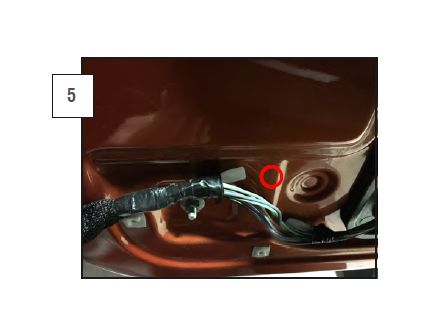
Step 5: Drill a pilot hole in the location seen above followed by a 1/2” hole. **Note: Paint any exposed metal. Then insert the supplied grommet.
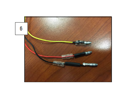
Step 6: Crimp on the bullet style connectors to the wires exiting the mirror. First slide the short clear rubber boot on the red, yellow, and black wires. Followed by a ½” piece of shrink wrap. Crimp on the male bullet connector on each of the wires, then shrink the shrink wrap over the crimp, then slide the rubber boot over the crimp. Repeat on all wires on each mirror.
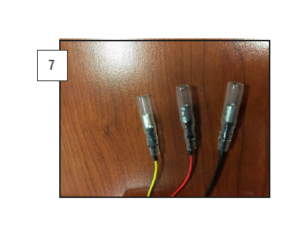
Step 7: Connect the supplied loose wire following the same order as in step 6 except you will be using the large rubber boot and the female connector.
Step 8: Once both sides of the connections are crimped, press them together. Red to red, yellow to yellow, and black to black. Insert the wire through the drilled holes and feed the wires down the door cavity and out the hole drilled in the bottom of the door. Leave enough slack in the wires so that you can remove your mirrors if needed. **Note: Don’t leave too much slack or the wires get caught in the window track.
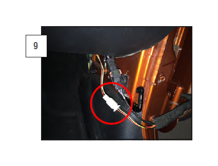
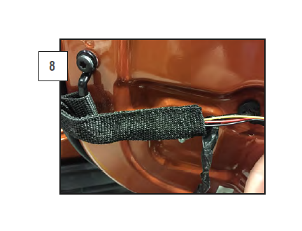
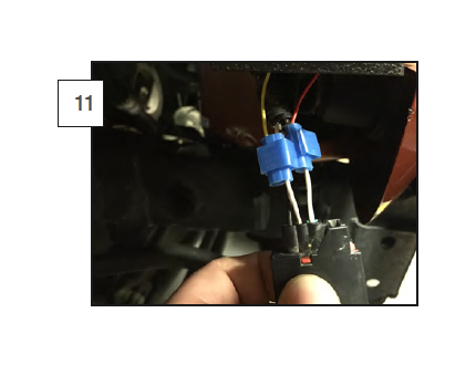
Step 9: Feed the wires through the factory door strap. Ensure there is enough slack in the wires that the door can be opened completely. Next, you will need to cut the wires and install the provided plug so that you can disconnect the mirror wiring if you remove your doors. Crimp the female spade connectors on the door wires. Insert the female spades into the (4) pin connector making sure they click in and are secure. Crimp on the male spades and press them into the male side of the plug ensuring the orientation of the wires will match up with the female connector. Plug both ends together.
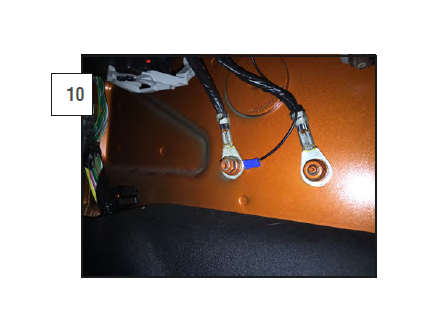
Step 10: Locate a suitable ground location, trim the wire to length and crimp the blue ring terminal on the end of the black wire, bolt the wire to the ground location.
Step 11: Feed the Red and Yellow wire through a suitable firewall grommet to the turn signal plug wiring. Secure the length of the wire, trim if needed. Red lead to turn signal 12v power. And the optional yellow lead to the running light 12v supply.
Reference your vehicles wiring diagrams for the correct colors.

