FREE 1 to 3-Day Delivery on Orders $149+ Details

How to Install Pro Comp Steering Stabilizer, Large Cylinder on your Wrangler
PLEASE NOTE:
Tire and wheel choice is crucial in assuring proper fit performance and the safety of your Pro Comp equipped vehicle. For this application a wheel not to exceed 7” in width with a maximum backspacing of 3.5 must be used. Diameter of wheel may be any of the following 2 choices, 15” or 16”. Any other diameter, either smaller or larger, will not be endorsed as acceptable by Explorer Pro Comp and will void any and all warranties, written or implied. In addition, a quality tire of radial design, not to exceed 31” tall x 10.50” wide is recommended.
BEFORE YOU BEGIN:
❑ Read the instructions and study the illustrations before attempting installation. Separating the parts according to the areas where they will be used and placing the hardware with the brackets before you begin will save installation time.
❑ Check the parts and hardware against the parts list to assure that your kit is complete.
❑ Always wear safety glasses when using power tools.
DISASSEMBLY:
1) Raise and suitably support the vehicle with jackstands. Support the axle with a floorjack. Remove the wheels and tires.
2) Mark and disconnect the front prop shaft at the axle as shown in ILLUSTRATION 1.
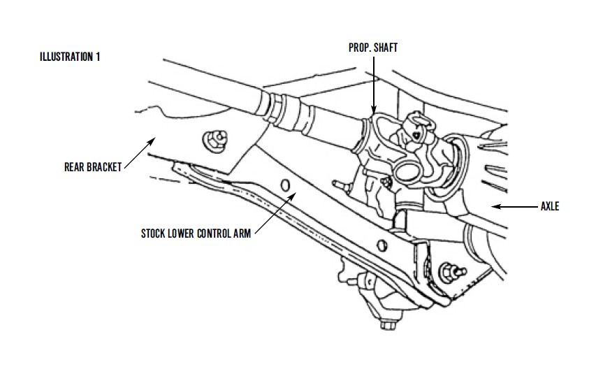
3) Disconnect the stock lower control arm at the axle and the rear bracket and remove. Refer to ILLUSTRATION 2.
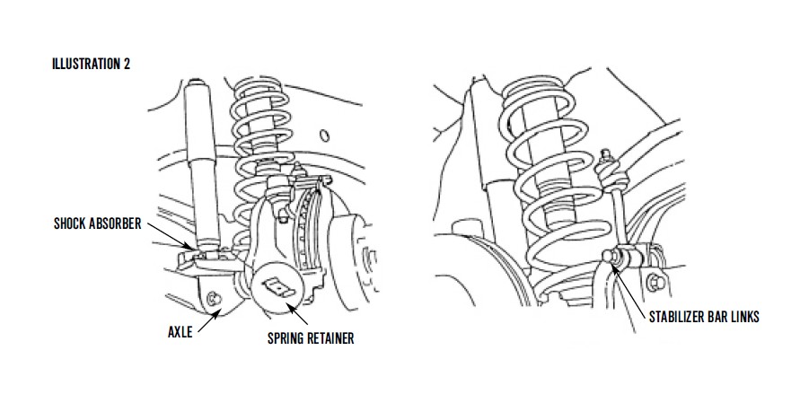
4) Disconnect the stabilizer bar links and the shock absorbers at the axle as shown in ILLUSTRATION 2. Remove front shocks.
5) Disconnect the track bar at the axle bracket.
6) Disconnect the drag link at the pitman arm.
7) Lower the axle assembly, loosen the spring retainers and remove the front springs.
INSTALLATION:
1) Install the new front springs and tighten the retainers.
2) Raise the axle into position.
3) Insert the bushings and sleeves, with grease, into the new lower control arms as shown in ILLUSTRATION 3.
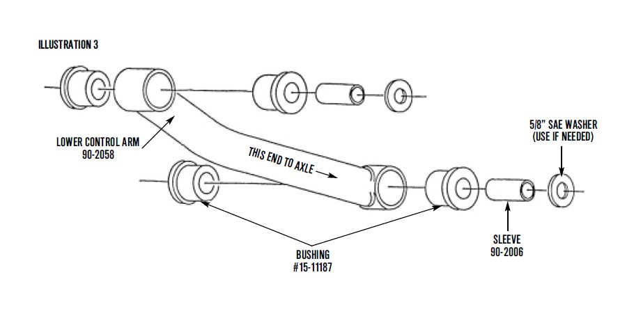
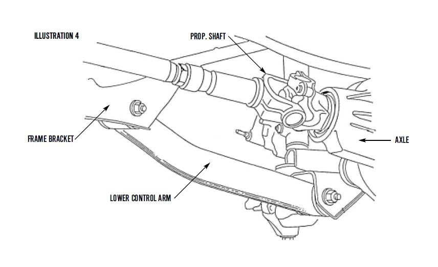
4) Position the lower control arms in the front and rear brackets and install using the existing bolts and nuts and the supplied washers if needed. See ILLUSTRATION 3 and 4.
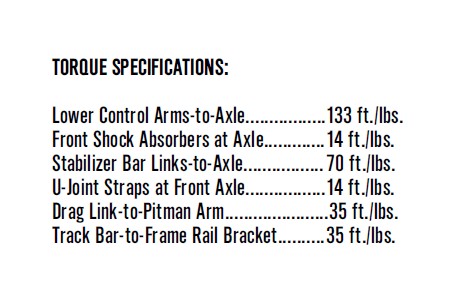
5) Tighten the mounting bolts with a torque of 180 Nm (133 ft./lbs.)
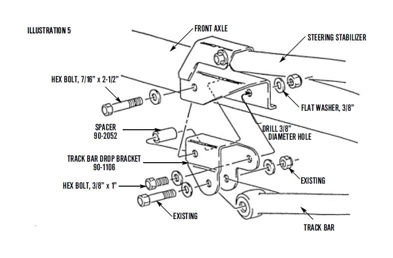
6) Position the track bar drop bracket, 90-1106 as shown in ILLUSTRATION 5. Mark the hole location on the axle bracket and drill 3/8” hole. Connect the track bar drop bracket to the axle bracket and the stabilizer bar links and shock absorbers to the axle. Refer back to ILLUSTRATION 2 if necessary.
7) Connect the front drive shaft to the axle. See ILLUSTRATION 4.
INSTALLATION OF REAR ADD-A-LEAF:
❑ To perform the installation properly, you must use two large c-clamps or a large vise to contain the elastic potential energy stored in a leaf spring when the center bolt is removed.
❑ A new add-a-leaf will be placed in the spring assembly in a progressive pyramid shape.
EXAMPLE: If your #1 leaf is 32” long and your #2 leaf is 24” long and the new add-a-leaf is 28” long, place the new add-a-leaf between leaves #1 and #2.
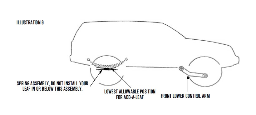
❑ Some springs will have a factory helper spring consisting of one or more flat or nearly flat leaves installed at the bottom of the leaf pack. See ILLUSTRATION 6. NOTE: DO NOT INSTALL YOUR ADD-A-LEAF SPRING IN OR BELOW THE HELPER SPRING ASSEMBLY.
1) Raise the rear of the vehicle, support the frame with jackstands and remove the rear wheels.
2) With a floorjack, raise the rear axle enough to relieve tension on the shock absorbers and remove them. Disconnect the axle vent hose from the axle housing.
3) Making sure the axle is well supported, remove the axle u-bolts and hardware. Next, remove the spring eye bolts and shackles, then remove the springs from the vehicle.
4) Using c-clamps or a large bench vise, hold the spring assembly securely together.
5) If applicable, remove any spring leaf alignment clamps. Using vise grips to hold the head of the center bolt, loosen and remove it. If the bolt has rusted, a hammer and drift punch may be used to drive it out.
6) Carefully remove c-clamps or open vise and lay unassembled spring aside.
7) With a small amount of grease applied to both ends of the add-a-leaf, reassemble leaf springs with add-a-leaf in place.
8) Loosely assemble the completed spring assemblies into their respective axle mounts. Replace the U-bolts, nuts and washers and torque to the factory specifications. Now reinstall spring eye bolts and shackles and torque to factory specifications.
9) Cycle steering lock to lock and inspect steering, suspension and driveline systems for proper operation, tightness and adequate clearance. Recheck brake hose/fittings for leaks. Be sure all hoses are long enough. Brakeline hose support kit #90-6029 is included with this kit. Use as needed.
10) Install the wheels and tires. Remove the jackstands and lower the vehicle.
CASTER:
Caster should be checked using wheel alignment equipment. If caster is incorrect, adjustment can be made by adding or removing shims at rear of the lower control arms.
FRONT WHEEL ALIGNMENT:
The alignment should be checked and adjusted. To ensure correct alignment, the following inspection is recommended:
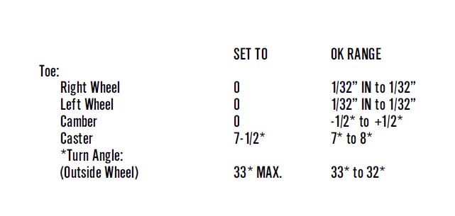
❑ This angle may be reduced as to allow 0.5 inches minimum.
❑ Adjust Headlights.