 FREE 1 to 3-Day Delivery on Orders $149+ Details

How to Install a Pro Comp 2.5 in. Lift Kit Without Shocks on your 1987-1995 Jeep Wrangler YJ
PLEASE NOTE WITH 4” SUSPENSION:
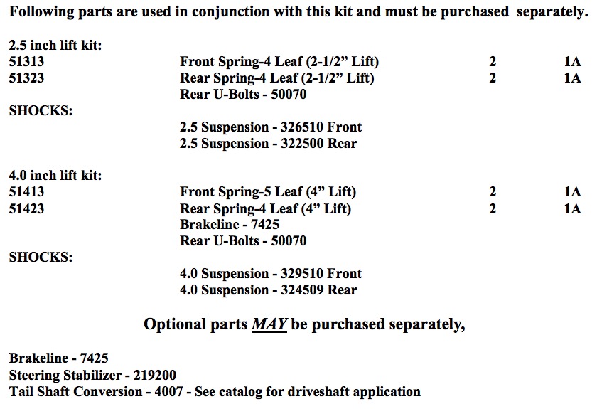
Tire and wheel choice is crucial in assuring proper fit performance and the safety of your Pro Comp equipped vehicle. For this application a wheel not to exceed 8” in width with a maximum backspacing of 3.5” must be used. Diameter of wheel may be any of the following 2 choices, 15”, 16”. Any other diameter, either smaller or larger, will not be endorsed as acceptable by Pro Comp Suspension and will void any and all warranties, written or implied. In addition, a quality tire of radial design, not to exceed 33” tall x 12.50” wide is recommended.
PLEASE NOTE WITH 2 1/2” SUSPENSION:
Tire and wheel choice is crucial in assuring proper fit performance and the safety of your Pro Comp equipped vehicle. For this application a wheel not to exceed 8” in width with a maximum backspacing of 3.5 must be used. Diameter of wheel may be any of the following 2 choices, 15”, 16”. Any other diameter, either smaller or larger, will not be endorsed as acceptable by Pro Comp Suspension and will void any and all warranties, written or implied. In addition, a quality tire of radial design, not to exceed 31” tall x 10.5” wide is recommended.
Introduction:
♦ This installation requires a professional mechanic!
♦ We recommend that you have access to a factory service manual for your vehicle to assist in the disassembly and reassembly of your vehicle. It contains a wealth of detailed information.
♦ Prior to installation, carefully inspect the vehicle’s steering and driveline systems paying close attention to the tie rod ends, ball joints, wheel bearing preload, pitman and idler arm. Additionally, check steering-to-frame and suspension-to-frame attaching points for stress cracks. The overall vehicle must be in excellent working condition. Repair or replace all worn or damaged parts!
♦ Read the instructions carefully and study the illustrations before attempting installation! You may save yourself a lot of extra work.
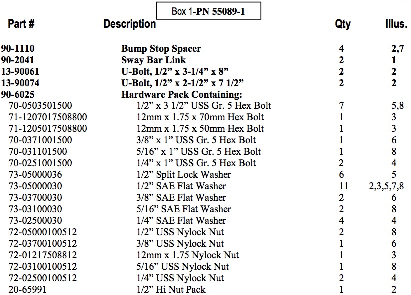
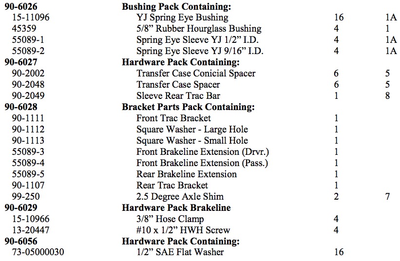
♦ Check the parts and hardware against the parts list to assure that your kit is complete. Separating parts according to the areas where they will be used and placing the hardware with the brackets before you begin will save installation time.
♦ Check the special equipment list and ensure the availability of these tools.
♦ Secure and properly block vehicle prior to beginning installation.
♦ ALWAYS wear safety glasses when using power tools or working under the vehicle!
♦ Use caution when cutting is required under the vehicle. The factory undercoating is flammable. Take appropriate precautions. Have a fire extinguisher close at hand.
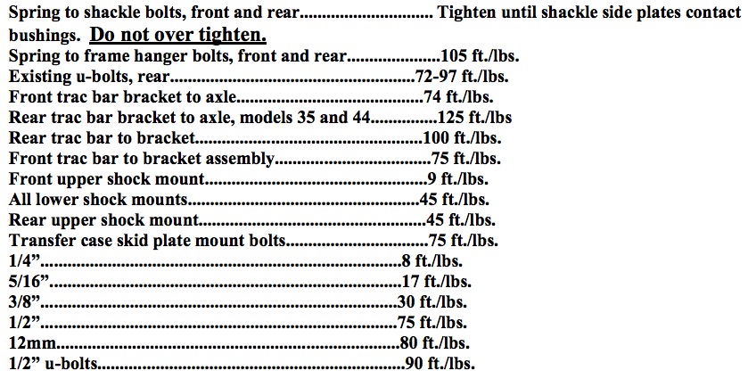
♦ Foot pound torque readings are listed on the Torque Specifications chart at the end of the instructions. These are to be used unless specifically directed otherwise. Apply thread lock retaining compound where specified.
♦ Please note that while every effort is made to ensure that the installation of your Pro Comp lift kit is a positive experience, variations in construction and assembly in the vehicle manufacturing process will virtually ensure that some parts may seem difficult to install. Additionally, the current trend in manufacturing of vehicles results in a frame that is highly flexible and may shift slightly on disassembly prior to installation. The use of pry bars and tapered punches for alignment is considered normal and usually does not indicate a faulty product. However, if you are uncertain about some aspect of the installation process, please feel free to call our tech support department at the number listed on the cover page. We do not recommend that you modify the Pro Comp parts in any way as this will void any warranty expressed or implied by the Pro Comp Suspension company.
Installation Instructions:
FRONT:
1) Secure and properly block the vehicle. Place the floor jack under the axle and then raise vehicle. Place the jack stands under the frame, behind the front springs.
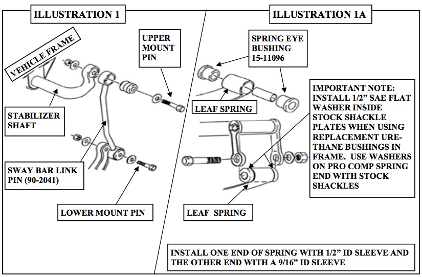
2) Remove the sway bar upper and lower mount pins, shocks, wheels and tires. Remove the bolts attaching the front brake lines to the top of the frame. Using the same mount pins, replace the stock sway bar link pins with the new link pins (90-2041) and the hour glass bushings (15-11083) as shown in ILLUSTRATION 1.
3) Supporting the front axle, remove the front trac bar bolt at the axle. Relieve the front springs by lowering the floor jack at this time.
4) Remove the front U-bolts and the supporting front axle, remove the spring hanger and shackle bolts and save them for re-installation later
5) Install bushings and sleeves into the spring eyes. Be sure to install one 1/2” ID sleeve and one 9/16” ID sleeve per spring.
6) Install the front springs with 1/2” ID sleeves into the spring shackle, as shown in ILLUSTRATION 1A.
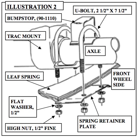
7) Lower the axle onto the springs, placing the front bumpstops (90-1110) over the axle tube. Install the new, longer U-bolts over one side of the bumpstops and place the larger I.D. U-bolts over the axle tube castings (see ILLUSTRATION 2). Re-install the spring retainer plate using 1/2” flat washers and 1/2” fine high nuts. Tighten U-bolts to 90 ft./lbs.
FRONT TRAC BAR MODIFICATION:
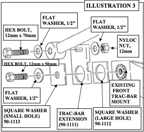
8) Referring to ILLUSTRATION 3, install the large hole square washer (90-1112) over the trac bar mount on the axle. Place the front trac bar extension bracket (90-1111) on the same mount with the slotted hole at the top of the bracket. Place the 12mm x 70mm bolt and 1/2” flat washer through the small hole square washer (90-1113) and into the assembly on the axle. Install the 1/2” washer and 12mm nut on the backside and tighten the assembly to 80 ft./lbs. Allow the trac bar to hang freely until the vehicle is sitting on the ground.
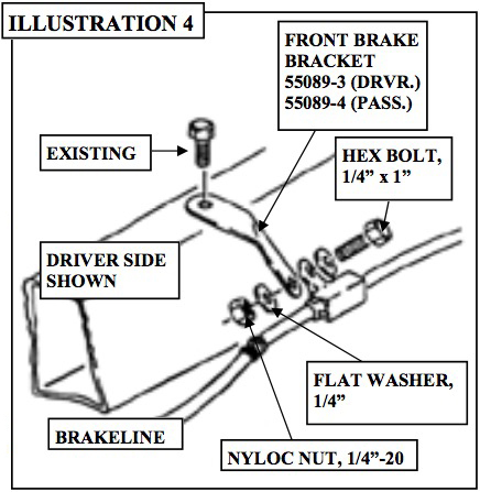
9) Install the two front brake bracket extensions (55089-3/Drvr.) and (55089-4/Pass.) where the brake lines were mounted to the frame using the existing bolts. Use the 1/4” x 1” hex bolts, washer and nuts to attach the original brake line brackets to the bracket extensions on the other end. Refer to ILLUSTRATION 4.
10) Install the shocks, wheels and tires. Use the 3/8” pal nuts on the upper shock mounts.
11) Lower the vehicle to the ground, tighten all spring mount bolts and re-install the sway bar lower mount pins. Tighten all fasteners to required torque specifications (see listing on last page of instruction sheet).
12) Referring again to ILLUSTRATION 3, install the 12mm x 50mm bolt and the 1/2” washer through the trac bar and into the new bracket on the axle. Tighten to 75 ft./lbs.
TRANSFER CASE MODIFICATION:
13) Place the floor jack under the transfer case skid plate. Loosen the three adjustment mount bolts on the bottom side of the skid plate.
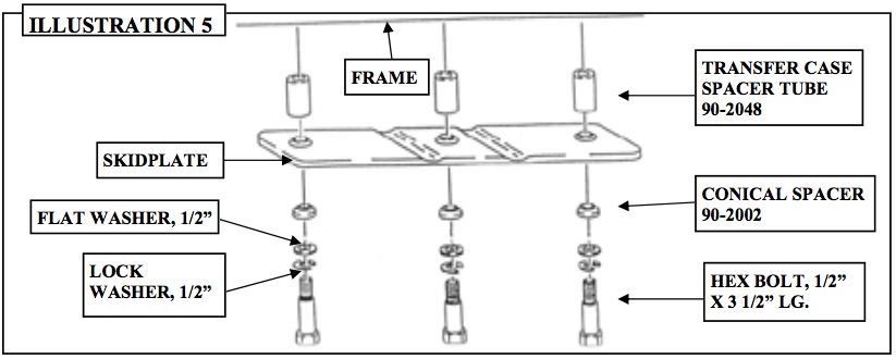
14) Remove the skid plate from the frame bolts (three on each side). Lower the assembly enough to place the transfer case spacer tubes (90- 2048) between the skid plate and the frame. Use the 1/2” x 3-1/2” hex bolts, with the hardware provided, to re-install the skid plate, as shown in ILLUSTRATION 5.
REAR:
1) Block the front wheels, place the floor jack under the rear axle and raise the vehicle. Place the jack stands under the frame on each side in front of the spring hanger. Remove the shocks, wheels and tires.
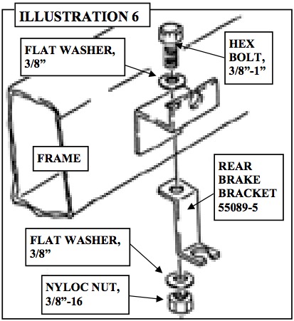
2) Remove the brake hose clip attaching the hose to the upper frame bracket. Remove the hose assembly from the bracket and install the rear brake bracket extension (55089-5) using the 3/8” bolt and washer in the frame bracket hole. See ILLUSTRATION 6. Re-align the brake line. Install it into the new bracket, attaching it to the existing clip. Tighten the 3/8” bolt to 20 ft./lbs.
3) Keeping slight pressure on the axle, remove the trac bar at the axle, axle u-bolts and spring. Refer back to steps 5 and 6, ILLUSTRATION 1 and 1A, for installation of the spring bushings and sleeves on the front installation. Follow these same instructions for the rear.
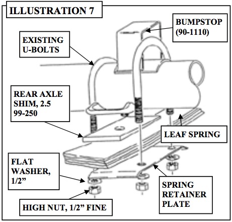
4) Place aluminum shims between the axle and the spring with the thick end of the shim toward the front of the vehicle and over spring bolts as shown in ILLUSTRATION 7. Lower the axle on to the shims and springs. Place the bump-stops on top of the axle tube and under the existing outer u-bolts.
Re-install the u-bolt plates and existing nuts and tighten to the required torque specifications. (See listing on the last page of the instruction sheet).
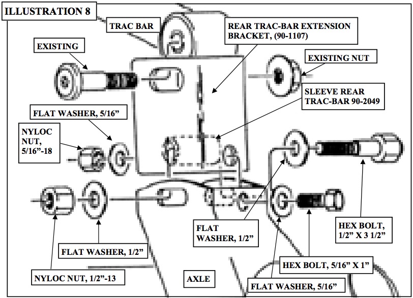
5) Install the rear trac bar extension bracket (90-1107) into the bracket on the axle with the slotted holes at the top. Install the 5/16” bolt, washer and nut into the small holes towards the outside of the vehicle. Refer to ILLUSTRATION 8. Tighten the bracket into place. Allow the trac bar to hang freely until the vehicle is sitting on the ground.
6) Referring again to ILLUSTRATION 8, place the rear trac bar sleeve (90-2049) inside the rear trac bar extension bracket, lining it up with the slotted holes. Install with 1/2” x 3-1/2” bolt, two 1/2” flat washers and the 1/2” nut, as shown. Tighten to 75 ft./lbs.
7) Install the shocks, wheels and tires.
CAUTION: Emergency cables may appear to be too tight on some models. Simply bend the bracket attaching the cables to the floor downward 90 degrees. This will allow the cables to move.
8) Lower the vehicle to the ground and install the existing bolt and washer through the upper slotted hole and through the trac bar. Install the existing nut. Tighten all fasteners to the required torque specifications for the spring shackles and hangers (see listing on the last page of the instruction sheet).
ADDITIONAL NOTES:
⇒ The weld at the trac bar may need to be ground to allow shock clearance.
⇒ Have the front end checked and aligned.
⇒ Check the shifters for proper engagement. The floor may require trimming or notching to allow full travel and engagement of the shifter.
TORQUE SPECIFICATIONS:
Notice to Owner operator, Dealer and Installer:
Vehicles that have been enhanced for off-road performance often have unique handling characteristics due to the higher center of gravity and larger tires. This vehicle may handle, react and stop differently than many passenger cars or unmodified vehicles, both on and off–road. You must drive your vehicle safely! Extreme care should always be taken to prevent vehicle rollover or loss of control, which can result in serious injury or even death. Always avoid sudden sharp turns or abrupt maneuvers and allow more time and distance for braking! Pro Comp reminds you to fasten your seat belts at all times and reduce speed! We will gladly answer any questions concerning the design, function, maintenance and correct use of our products.
Please make sure your Dealer/Installer explains and delivers all warning notices, warranty forms and instruction sheets included with Pro Comp product.
Application listings in this catalog have been carefully fit checked for each model and year denoted. However, Pro Comp reserves the right to update as necessary, without notice, and will not be held responsible for misprints, changes or variations made by vehicle manufacturers. Please call when in question regarding new model year, vehicles not listed by specific body or chassis styles or vehicles not originally distributed in the USA.
Please note that certain mechanical aspects of any suspension lift product may accelerate ordinary wear of original equipment components. Further, installation of certain Pro Comp products may void the vehicle’s factory warranty as it pertains to certain covered parts; it is the consumer’s responsibility to check with their local dealer for warranty coverage before installation of the lift.
Warranty and Return policy:
Pro Comp warranties its full line of products to be free from defects in workmanship and materials. Pro Comp’s obligation under this warranty is limited to repair or replacement, at Pro Comp’s option, of the defective product. Any and all costs of removal, installation, freight or incidental or consequential damages are expressly excluded from this warranty. Pro Comp is not responsible for damages and / or warranty of other vehicle parts related or non-related to the installation of Pro Comp product. A consumer who makes the decision to modify his vehicle with aftermarket components of any kind will assume all risk and responsibility for potential damages incurred as a result of their chosen modifications. Warranty coverage does not include consumer opinions regarding ride comfort, fitment and design. Warranty claims can be made directly with Pro Comp or at any factory authorized Pro Comp dealer.
IMPORTANT!
To validate the warranty on this purchase please be sure to mail in the warranty card.
Claims not covered under warranty-
• Parts subject to normal wear, this includes bushings, bump stops, ball joints, tie rod ends and heim joints
• Discontinued products at Pro Comp’s discretion
• Bent or dented product
• Finish after 90 days
• Leaf or coil springs used without proper bump stops
• Light bulbs
• Products with evident damage caused by abrasion or contact with other items
• Damage caused as a result of not following recommendations or requirements called out in the installation manuals
• Products used in applications other than listed in Pro Comp’s catalog
• Components or accessories used in conjunction with other manufacturer’s systems
• Tire & Wheel Warranty as per Pro Competition Tire Company policy
• Warranty claims without “Proof of Purchase”
• Pro Comp Pro Runner coil over shocks are considered a serviceable shock with a one-year warranty against leakage only. Rebuild service and replacement parts will be available and sold separately by Pro Comp. Contact Pro Comp for specific service charges.
• Pro Comp accepts no responsibility for any altered product, improper installation, lack of or improper maintenance, or improper use of our products.
E-Mail: [email protected]
Website: www.explorerprocomp.com
Fax: (619) 216-1474
Ph: (619) 216-1444

