 FREE 1 to 3-Day Delivery on Orders $149+ Details

How to Install Poison Spyder Extra Wide Front Crusher Fender Flares - Aluminum on your Wrangler
Tools Required
- 1/2” open end wrench
- 1/4” drive ratchet, 10mm socket, extension
- Small screw-driver or spud bar
- Drill motor with 1/8” & 21/64” drill bits
- 3/16” hex key
- Removal tool for push-in retainer clips (or small screwdriver)
- Heavy shears or cut-off wheel
- Touch-up paint or clear coat
APPLICATIONS
These installation instructions apply to the following Poison Spyder products:
17-03-030 JK Front Crusher Flares - Standard Width - Steel
17-03-030-ALUM JK Front Crusher Flares - Standard Width - Aluminum
17-03-031 JK Front Crusher Flares - Narrow Width - Steel
17-03-031-ALUM JK Front Crusher Flares - Narrow Width - Aluminum
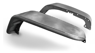
17-03-032 JK Front Crusher Flares - Extra Wide - Steel (shown)
17-03-032-ALUM JK Front Crusher Flares - Extra-Wide - Aluminum
PARTS LIST
Please check your packages immediately upon arrival to ensure that everything listed is included, and to check for damage during shipping. If anything is missing or damaged, call Poison Spyder at (951) 849- 5911 as soon as possible.
(1) Driver side front JK Crusher Flare
(1) Passenger side front JK Crusher Flare
(1) Driver side upper sub-frame bracket
(1) Passenger side upper sub-frame bracket
(2) Lower sub-frame bracket
(2) Forward Crusher Flare rubber gasket
(2) Rearward Crusher Flare rubber gasket
(6) Inner fender liner “L” bracket
(1) JK Front Crusher Flares Hardware Kit
PN: HWKIT-17-03-030 includes:
(6) 1/4-20 U-Nut Clip
(10) 1/4-20 X 3/4 SS Button Head Cap Screw
(10) 1/4” SAE Hardened Flat Washer
(4) 1/4-20 Gr8 Nylon Insert Lock Nut
(10) 5/16-18 U-Nut Clip
(10) 5/16-18 X 1 SS Flat Head Cap Screw
(20) 5/16-18 X 3/4 SS Flat Head Cap Screw
(28) 5/16” SAE Hardened Flat Washer
(24) 5/16-18 Gr8 Nylon Insert Lock Nut
(4) 5/16-18 X 3/4 Gr8 Hex Head Cap Screw
(4) 5/16 X 1-1/2 O.D. Fender Washer
IMPORTANT INFORMATION
Crusher Flares come as unpainted, bare steel or aluminum. You will want to either powder coat or paint prior to final installation, however it is very important to PRE-INSTALL the unpainted product first, following these instructions, BEFORE painting or powder coating any of the components! This will ensure that all parts are correct and any incidental trimming or drilling will have been done prior to coating. Also, it will give you a practice run to familiarize yourself with the process, to lessen the likelihood of damaging the finish during final installation.
Poison Spyder Customs, Inc. is NOT RESPONSIBLE for paint or powder coating costs, damage to paint or powder coating, or costs associated with inadvertently painting or powder coating components that are defective or were shipped or assembled in error. It is the customer’s responsibility to pre-install and verify that all parts are correct prior to paint or powder coat.
On STEEL Crusher Flares, it is important to properly seal all of the seams where metal pieces join without a weld. This includes both the outside and inside seam where the top plate meets the outer tube. The reason is to prevent moisture from entering these hard-to-reach places and causing rust, and to prevent moisture from subsequently leaking back out of these areas and bringing rust reside with it, on to your paint or powder coat finish. There are many products available to seal these areas, from rubberized undercoating products to silicone sealant. If powder-coating, make sure the sealing method is one that is tolerant of the high temperatures used in the powder coat baking process. Consult your professional painter or powder coater for best suggestions.
INSTALLATION PROCEDURE
The following procedure is for preparation and installation of the JK Crusher Flare on one side of the Jeep. Once complete, repeat the procedure for the other side.
1. Park vehicle on a level surface and set the emergency brake. You will want to wear eye protection beyond this point in time.
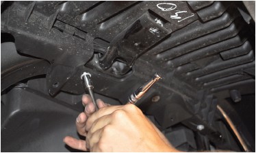
2. Remove the inner fender by using a 10mm socket to remove the factory hex head bolts, and a push-in retainer removal tool to pop out the plastic push-in retainers.
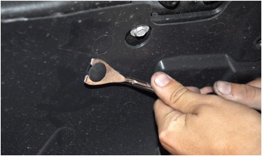
Try not to damage the inner fender or the plastic retainers. Set the inner fender, all of the plastic retainers and hex head bolts aside, as some will be re-used during the installation process.
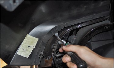
3. Disconnect the side marker lamp by pulling the wiring harness plug out of the lamp socket.
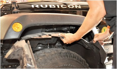
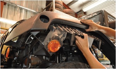
4. Remove the plastic fender/flare support. You may need to remove more hex head bolts and/or plastic retainer clips.
Set the fender/flare support aside. It will not be re-used.
5. Remove the stock fender flare. There will be several more plastic retainer clips to remove in order to remove the flare.
Some of these retainer clips are of a different type than the others, and are tougher to remove. Be careful when removing them not to bend or deform the Jeep body sheet metal. Set the stock fender flare aside. It will not be re-used.
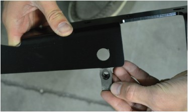
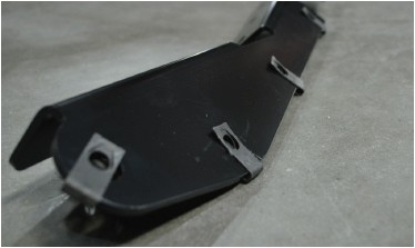
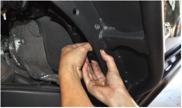
6. Locate the Upper Sub-Frame Bracket for the side you are working on. Note that there is a left and right bracket. Use the photos in the following steps to properly identify the correct bracket and its orientation for the side you are working on. Install a 5/16-18 U-nut into each of the five (5) holes along the top edge of the bracket. Orient the u-nut so that the threaded extrusion is toward the inside of the L-shape of the bracket, as shown in the following photos.
7. Align the Upper Sub-Frame Bracket as shown in figure 22, and slide it upward between the outer fender sheet metal and the inner tub brace. It may be a tight fit, and could require a firm shove or two. Position it so that the threads of the u-nuts are roughly aligned with the 5 corresponding holes in the outer fender.
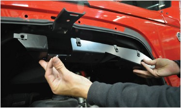
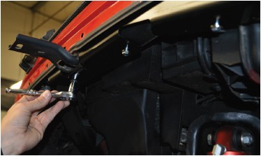
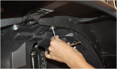
Re-use three (3) of the OEM metric hex head bolts to attach the Upper Sub-Frame Bracket, bolting them through the holes along the bottom of the bracket.
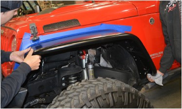
8. Apply masking tape to the Jeep’s fender, around the area where the Crusher Flare will be installed, to protect the paint finish of the surrounding sheet metal while working with the metal flares.
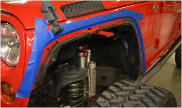
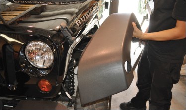
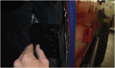
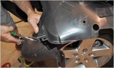
9. Pre-install the Crusher Flare. Place it against the Jeep and line up the bolt holes. It will rest somewhat on the stock fender brace to make this task easier. Even with masking tape in place, be careful while handling the Crusher Flare, to keep it from contacting the exterior finish of the Jeep and scratching the paint.
Install two of the 5/16-18 X 3/4 stainless steel flat head cap screws, one at the rear and one at the front end of the Crusher Flare. The one at the front will need to be backed by a flat washer and lock nut (supplied in the hardware kit)
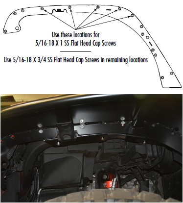
Continue installing hardware into the remaining available holes. Note the following diagram which shows the locations to use the 1” long flat head cap screws. The remaining holes get the 3/4” long flat head cap screws. (Note: several of the hole locations will need to be drilled out, and will not be able to accept hardware yet-leave these holes unused at this time.)
Observe how the Crusher Flare sits into the pocket in the fender sheet metal, and make any necessary adjustments to ensure that it is perfectly aligned as the hardware is tightened. The goal is to maintain a uniform gap along the top of the Crusher Flare where it sits into the fender pocket, from front to back.
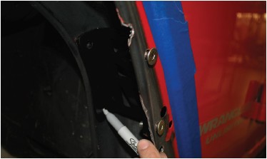
10. Use a fine tip felt marker to mark the blank mounting holes which will need to be drilled out.
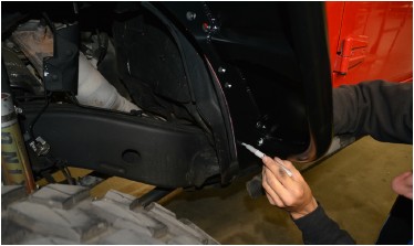
Use a scribe to mark along the fender sheetmetal that extends into the wheel opening, beyond the mounting plate of the Crusher Flare, both at the back of the wheel opening...
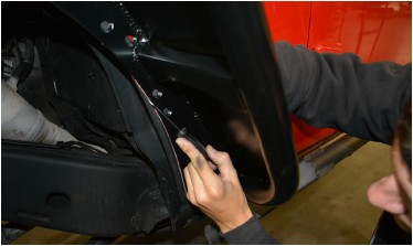
...and at the front of the wheel opening.
11. Remove the Crusher Flare AND the Upper Sub- Frame Bracket from the Jeep. You’ll now see the marks you made for drilling the extra mounting holes and trimming sheet metal around the wheel opening.
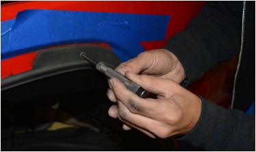
12. Use an auto-punch or a center punch with small hammer to punch a pilot mark into the center of each of the hole marks you made. If you use a hammer and punch, be careful not to strike the punch too hard, as the sheet metal is thin and bends easily.
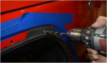
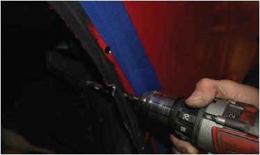
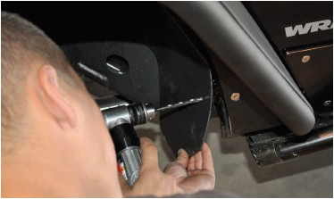
13. Drill a pilot hole at each drill mark using a 1/8” bit. Note that two of the hole marks will land on the edge bead of the sheet metal. You must be especially careful when starting to drill these two holes, as the bit will want to walk off of the bead. Hold the drill so that the bit is angled directly into the edge of the bead, wherever it happens to be along the curvature of the bead, in order to prevent walking.
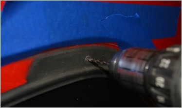
Once all of the pilot holes are drilled, switch to the 21/64” bit and re-drill each hole out to its final size. Be careful when drilling, as the larger bit may want to grab the thin sheet metal and deform it. After the holes are drilled, apply some touch-up paint or clear coat to the bare metal of the hole edges to protect them from rust.
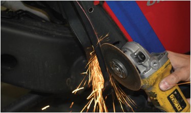
14. Use a pneumatic or electric cut-off wheel or your cutting device of choice, to trim the fender sheet metal along the scribe marks made in the previous steps.
15. Use a sandpaper flap wheel or file to de-burr and smooth the cut edges of the sheet metal. Use touch-up paint to coat the bare metal at the edges of all cuts and drilled holes, to prevent rust.
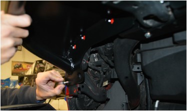
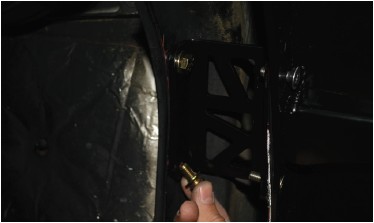
16. Install the Lower Sub-Frame Brackets into the area between the outer fender sheet metal and the inner tub bracing, as shown.
The holes on the Lower Sub Frame Bracket can only align with two specific holes in the outer fender, so position it until you have it properly aligned with the two holes, then hold it temporarily in place by sliding two fasteners from the hardware kit into these two holes.

17. With the Lower Sub-Frame Bracket temporarily in place, use the fine-tip felt marker to mark the two hole locations in the inner tub brace. Then remove the bracket.
18. Follow the same procedures as in steps 9 and 10 to punch and drill the two holes in the inner tub brace. Drill the 1/8” pilot hole first, then step up to the 3/8” bit. You will have to pass the bit through the hole in the outer fender to reach the inner tub brace.
Use touch-up paint to coat the bare metal at the edges of the drilled holes, to prevent rust.
19. Reinstall the Upper Sub-Frame Bracket and the Crusher Flare, using the same hardware as before. It may be necessary to use a small screw-driver or spud bar to finish aligning the u-nuts on the Upper Sub-Frame Brace with the newly drilled holes in the outer fender. The u-nuts “float” somewhat and have some room for adjustment.
20. Re-install the Lower Sub-Frame Bracket. Use two 5/16-18 X 3/4 hex head cap screws with flat washers and nylon insert lock nuts to attach the bracket to the inner tub brace. Keep the holes in the bracket properly aligned with the holes in the outer fender as you tighten the bolts.
21. If you wish to install the supplied rubber gaskets, remove all but one of the flat head cap screws along the top edge of the Crusher Flare. Loosen the last screw enough to separate the Crusher Flare from the fender sheet metal slightly.
22. Note that there are two rubber gaskets per side- front and rear-and you can identify them by shape. With the Crusher Flare loosely installed, slide the rubber gasket in between the Crusher Flare and the Jeep’s sheet metal, and align it with the outer edge of the Crusher Flare. See that the holes in the rubber gasket are aligned with the bolt holes in the Crusher Flare. Re-tighten all hardware.
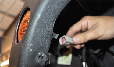
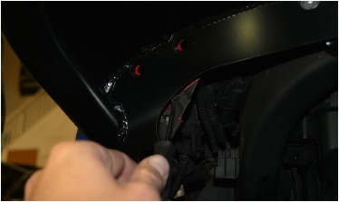
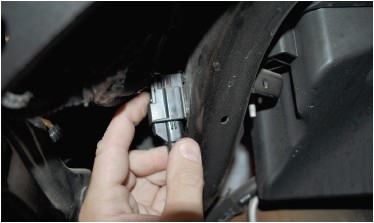
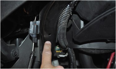
23. (OPTIONAL) If you are installing LED side marker lights (sold separately), do so now. Remove the OEM marker light pigtail from the harness, at the plug as shown in the photo. Press on the tang with your index finger, as shown in the photo, to free the plug from the socket while pulling.
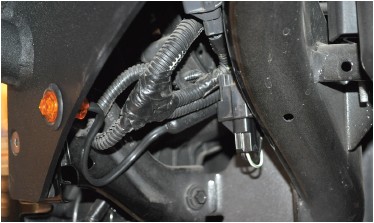
Cut the OEM pigtail approximately 2” from the plug you just removed, and discard the opposite end. Use butt connectors to attach the OEM pigtail plug to the LED pigtail. Note that on the LED’s sold by Poison Spyder, the white wire is ground and the black wire is positive. Use a test light to determine which wire on the factory harness is ground and which is positive, then make the appropriate connections. Use heat-shrink wrap to protect the connection. Install the LED into the small hole in the forward corner of the Crusher Flare mounting plate using the supplied rubber grommet. Then plug the pigtail (now with the OEM plug) into the socket in the factory harness. Use a couple of nylon tie-wraps (zip-ties) to secure any slack in the pigtail wiring.
NOTE: If you intend to trim and re-use the factory inner fender liner, proceed to the following steps. If you do not intend to use it, you are finished and may continue by repeating the entire procedure for the remaining side.
24. Install three (3) Inner Fender Liner “L” Brackets at the three bolt locations denoted in the following diagram.
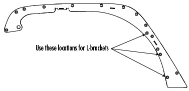
The flat head cap screw should pass through the hole in the Crusher Flare base plate, then through the slotted hole in the “L” bracket (the L-bracket sits behind the flare base plate). The L-bracket should form a 90-degree angle, with the
25. Install a 1/4-20 U-Nut Clip into the remaining hole of each of the three “L” brackets. Orient the u-nut so that the threaded extrusion is toward the inside of the L-shape of the bracket
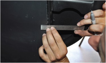
26. Adjust the “L” bracket so that the flat surface of the bracket (and flush side of the U-Nut) is parallel with, but recessed between 1/16” and 1/8” back from, the edge of the Crusher Flare mount plate. Tighten the lock nut on each bracket.
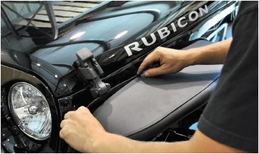
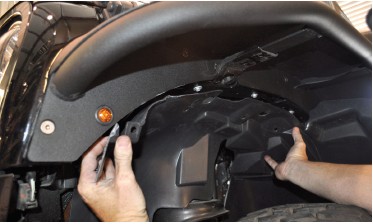
27. To re-install the OEM inner fender liner, it must first be trimmed to fit. Be aware that proper trimming of the OEM inner fender liner requires care, attention and patience. We cannot provide a cut template for this, so you will have to rely on your own test-fitting, marking, cutting and trimming to provide the best fit. Begin by holding the plastic inner fender up in the wheel well, as close to its mounting position as possible. Use a fine-tip felt marker to designate your initial rough cut lines. Be conservative, only mark and cut away the most obviously unneeded parts first.
Once the large parts are out of the way, test-fit the inner fender again and make marks for more fine-tuned trimming. It should take several of these steps to finally get it right. Just be sure not to cut away too much in any step, be patient and you will eventually get it just right.
28. Once the inner fender liner is trimmed to fit, attach it by first removing the two previously-installed bolts from Upper Sub-Frame Bracket that appear through the access holes in the inner fender liner. Remove each of these bolts, place one of the provided 5/16 fender washers under the head of each, then re-install and tighten.
29. At the rearward edge of the inner fender liner, mark where the holes in the “L” brackets are located behind the inner fender.
The inner fender liner is flexible plastic, and you will be able to pull it away enough to take your measurements. Mark the hole locations then drill the three holes with a 1/4” bit.
30. Install a 1/4-20 X 3/4 SS Button Head Cap Screw with 1/4” SAE Flat Washer at each of the three holes that were just drilled in the previous step. Insert the screw into the hole in the inner fender liner, and into the corresponding 1/4-20 U-Nut Clip that was installed in the “L” bracket in a previous step. Use a 5/32” hex key to firmly tighten each fastener. Be sure not to over-tighten and risk damaging the threads on the fasteners.
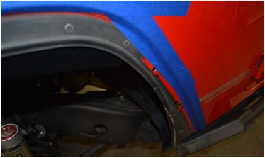
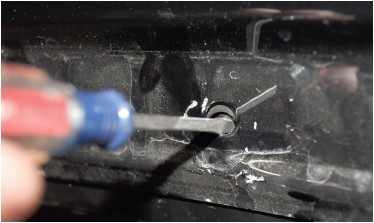
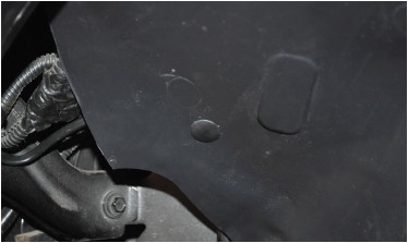
31. Toward the front of the inner fender liner, there is a small hole in the OEM tub frame brace, behind the inner fender liner, as shown in figure 37.
Transfer the location of this hole to the surface of the inner fender liner, mark and drill a corresponding hole with the 1/4” bit. Install one of the OEM plastic retainer clips at this location.
32. Repeat all procedures for the opposite side.
33. Remove the Crusher Flares from the Jeep to paint or powder coat, then re-install using the same procedures.
IMPORTANT: on STEEL Crusher Flares, it is important to properly seal all of the seams where metal pieces join without a weld. This includes both the outside and inside seam where the top plate meets the outer tube. The reason is to prevent moisture from entering these hard-to-reach places and causing rust, and to prevent moisture from subsequently leaking back out of these areas and bringing rust reside with it, on to your paint or powder coat finish. There are many products available to seal these areas, from rubberized undercoating products to silicone sealant. If powder-coating, make sure the sealing method is one that is tolerant of the high temperatures used in the powder coat baking process. Consult your professional painter or powder coater for best suggestions.
Congratulations, you have completed the installation of your Poison Spyder JK Crusher Flares!

