 FREE 1 to 3-Day Delivery on Orders $149+ Details

How to Install Poison Spyder BFH II Front Bumper w/ Brawler Bar - SpyderShell Armor Coat on your 07-18 Jeep Wrangler JK; 2018 Jeep Wrangler JL
Tools Required
- 3/4” wrench, socket & ratchet
- Soft dead blow hammer or mallet
- Reicprocating saw tih bi-metal blade OR pneumatic or electric cut-off wheel OR plasma cutter OR similar tool for cutting metal
- Angle grinder
- Phillips screwdriver
- C-clamps or bar clamps
- Measuring tape, square, straight-edge
- Fine-tip felt marker
- 1/2” drill bit and drill motor
- Primer and paint

Shop Parts in this Guide
IMPORTANT: Thank you for purchasing this Poison Spyder product. Please read through this entire document before proceeding with installation. If you are not confident in your mechanical skills, please seek the help of a professional to perform the installation. Check your packages immediately upon arrival to ensure that everything listed is included, and to check for damage during shipping. If anything is missing or damaged, or if you need technical assistance with any aspect of this installation, call Poison Spyder at (951) 849-5911 as soon as possible. This document last updated July 2017.
APPLICATIONS
These installation instructions apply to the following Poison Spyder products:
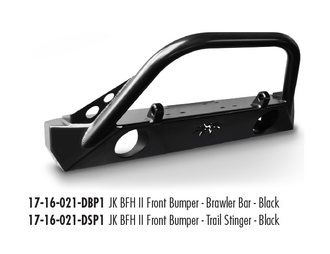
PARTS LIST
(1) JK BFH Front Bumper
(1) JK BFH Bumper Hardware Kit
PN: HWKIT-17-16-021 includes:
(4) 1/2-13 X 5-1/2 Gr8 Hex Head Cap Screw
(4) 1/2-13 All-Metal Lock Nut
(8) 1/2” SAE High Strength Flat Washer
(8) Self-Tapping Screw
(1) JK Vac Pump Relocation Bracket
(1) JK Swaybar Spacer Passenger Side
(1) JK Vac Pump Relo Hardware Kit
PN: HWKIT-17-16-100 includes:
(2) 1/4-20 X 1-1/2 SS Button Head Cap Screw
(2) 1/4-20 SS Nylon Insert Lock Nut
(4) 1/4 “SAE High Strength Flat Washer
BEFORE YOU BEGIN
The Poison Spyder Customs BFH bumper comes with SpyderShell™ Armor Coat finish. Protect the finish while installing by applying masking tape or protective film over areas of the bumper that are near drill holes or will be handled, or close to tools.
INSTALLATION PROCEDURE
1. Park the Jeep on a flat, level surface and set the parking brake.
2. Remove existing front bumper.
3. If your Jeep is equipped with factory fog lamps, these may be removed from the stock bumper and re-installed into the BFH™ II bumper. Use a Phillips screwdriver to remove the four (4) retaining screws from each lamp, on the back side of the bumper.
Install the factory fog lamps into the fog lamp mounts in the back side of the BFH™ II Front bumper, using the provided self-tapping screws. These sheetmetal screws will form their own threads as you drive them into the retaining rings on the Brawler bumper, so press firmly as you twist the screwdriver.
If the Jeep is a 2007-2011 year model, it should not require vacuum pump relocation, which is covered in the following steps. Skip the next 10 steps and continue at step 15.
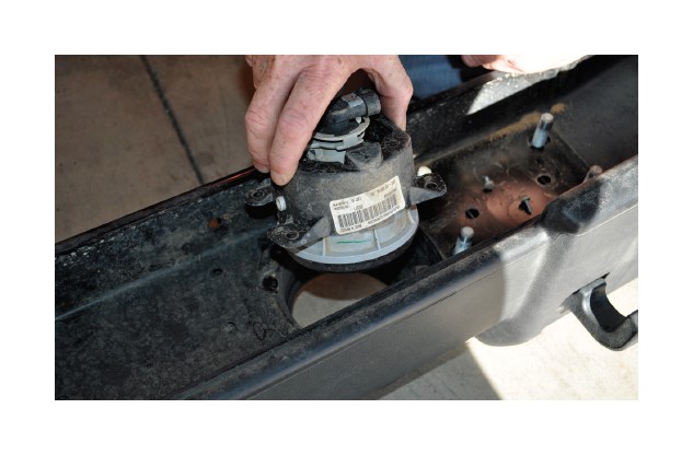
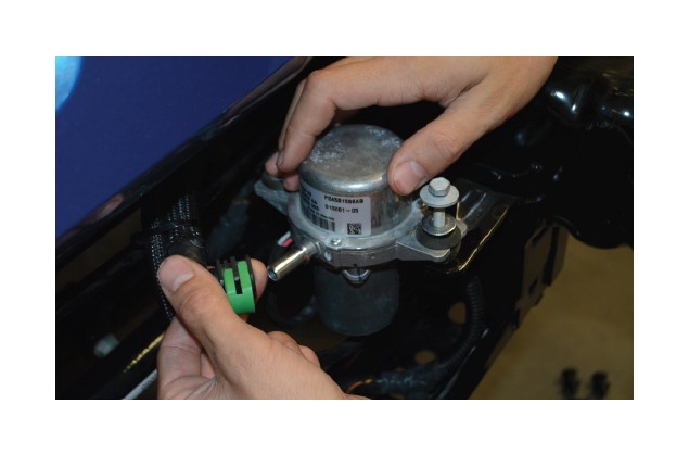
4. If the Jeep is a 2012 or later model with the vacuum pump located on the inner frame rail, it will need to be relocated using the JK Vacuum Pump Relocation Bracket (sold separately), Begin by removing the two bolts that hold the vacuum pump into the mount on the Jeep’s frame.
5. Disconnect both hoses from the vacuum pump.
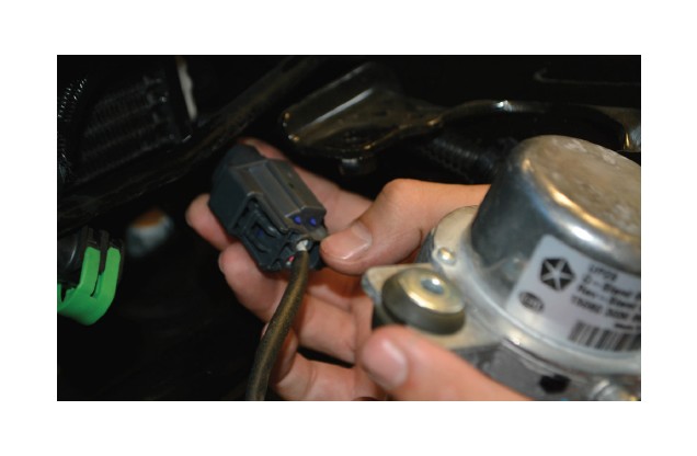
6. Disconnect the vacuum pump’s electrical wire pigtail from the vehicle wiring harness by separating the connector.
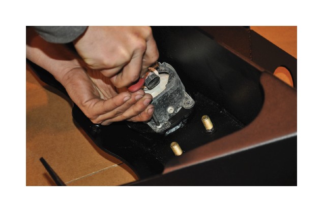
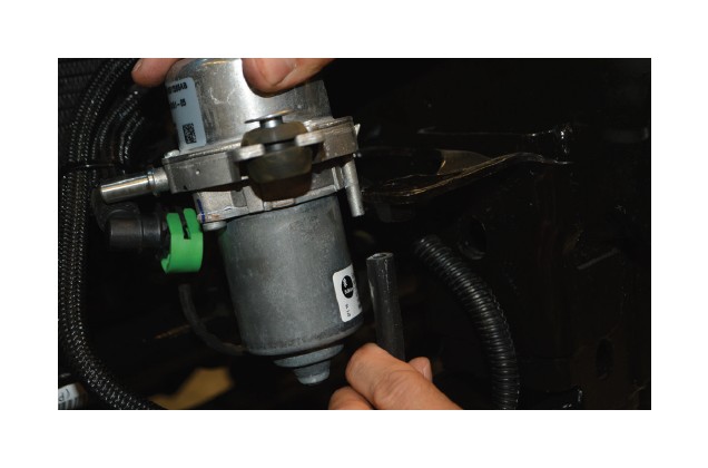
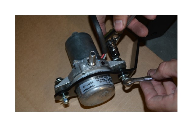
7. There are two rubber bushings in the mounting flanges on the vacuum pump, with steel sleeves inserted into these bushings. Remove the steel sleeves, then reinsert them into the rubber bushings from the opposite side of the mounting flange. This will move the flat washer surface of the steel sleeve to the other side of the rubber bushing.

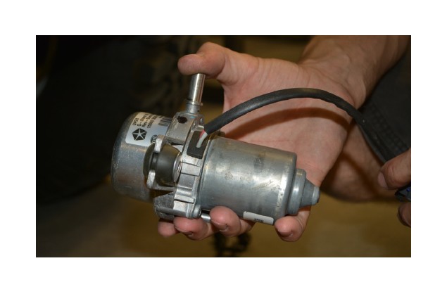
8. Attach the vacuum pump into the relocation bracket, oriented as shown in the photo. Use the supplied 1/4-20 X 1-1/2 SS Button Head Cap Screws, SS lock nuts and washers.
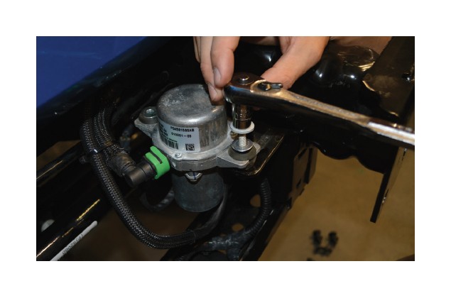
9. Loosen the two bolts that hold the sway bar bushing block to the underside of the driver side frame rail.
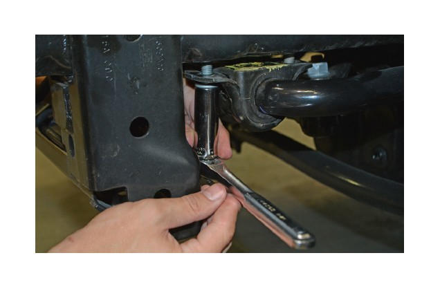
10. Insert the mount flange of the vacuum pump relocation bracket between the swaybar bushing block and the underside of the driver side frame rail. Reinstall and re-tighten the two swaybar bushing blocks.

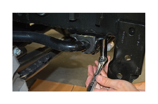
11. Loosen the two bolts that hold the sway bar bushing block to the underside of the passenger side frame rail, and insert the swaybar spacer in between the swaybar bushing block and the frame rail.
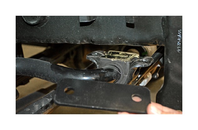
12. Reinstall and re-tighten the two swaybar bushing blocks.
13. Re-attach the two vacuum hoses to the canister. Re-attach the electrical pigtail to the wiring harness. Use zip-ties to secure any loose hoses or wiring.

14. Remove the “Crash Bar”. Use a torch, plasma cutter, pneumatic or electric cutoff wheel, reciprocating saw, or the cutting device of your choice. At each end of the Crash Bar there is a vertical bracket that attaches it to each frame rail. Cut these brackets off as close as possible where they meet the frame rail. Be careful not to cut INTO the frame rail.

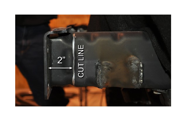
15. Measure 2” back, along the frame rail, from the front edge of the OE bumper mounting bracket. Use a square and/or straight edge to mark a straight, perpendicular cut line at this 2” measurement.

16. Use a reciprocating saw or other suitable cutting device to cut the frame rails off, along the cut line marked in the previous step.
17. Use a grinder to de-burr the cut edges and smooth down the remnants of the crash bar brackets. It will be important to get the outboard surfaces of the frame rails fairly smooth for proper fitment of the BFH bumper.
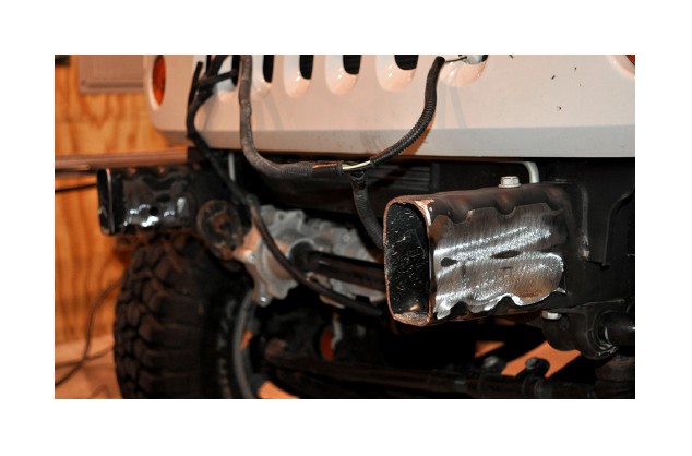
18. Apply primer and paint to the bare metal in the areas that were cut and grinded, including the cut edges of the frame rails. Properly coating these areas at this time will help to prevent rust in the future.
19. Remove the grille by opening the hood and removing the six Phillips head screws along the top of the grille. Reach behind the grille and disconnect the headlight and turn signal lamp sockets. Remove the grille while carefully disengaging the snaps along the bottom edge of the grille.
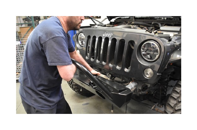
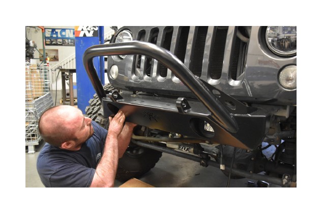
20. Place the BFH™ II Front Bumper on to the frame rails. Visually align the rearward, elongated bumper mounting slots with the existing holes in the frame rails. Use a soft dead-blow hammer, if necessary, to make the fine adjustments. Use C-clamps or bar clamps to hold the bumper tightly in place.
21. Use a drill motor and 1/2” bit to drill 1/2” holes through the frame rails at each of the mounting holes, using the bumper itself as your drill guide. Drill the upper holes from the top and the lower holes from underneath. Do not try to drill both the top and the bottom through the same hole in the bumper, as you may not get the holes properly aligned.
22. Install the supplied Grade 8 bolts with lock nuts and flat washers, into mounting holes, and tighten.
23. Re-install the grille by reversing the removal procedure.
24. If you installed the OE fog lamps into the BFH™ II bumper, plug the harness connectors back into the sockets in the back of each lamp. Secure the wiring harness in place by inserting the stock plastic harness clips into the three holes along the upper-rear flange of the BFH™ II bumper.
25. If installing the optional BFH™ Disco Skid, follow the instructions that came with the Disco Skid. If installing a winch with Poison Spyder Winch Fairlead Mount, follow the instructions included with the Winch Fairlead Mount.
Congratulations, you have installed your Poison Spyder Customs BFH II front bumper!

