 FREE 1 to 3-Day Delivery on Orders $149+ Details

How to Install Off Road Only LiteDOTs LED Taillights on your 1987-2006 Jeep Wrangler
Tools Required
- Phillips screwdriver
- 10mm socket
- extension and Ratchet
- 3/8" Socket
- extension and Ratchet
- Wire cutter
- Wire Stripper
- Heat gun (High heat hair dryer may work)
- Utility knife or other sharp knife
- 3/16" Allen wrench

Shop Parts in this Guide
This document designed to aid in installation of LiteDOT’s™ on Jeep TJ models, other models are similar.
NOTE: Installing LiteDOT’s™ on a Jeep where the 2 necessary mounting points have been modified will result in the installer having to make allowances or adjustments to fit LiteDOT’s™.
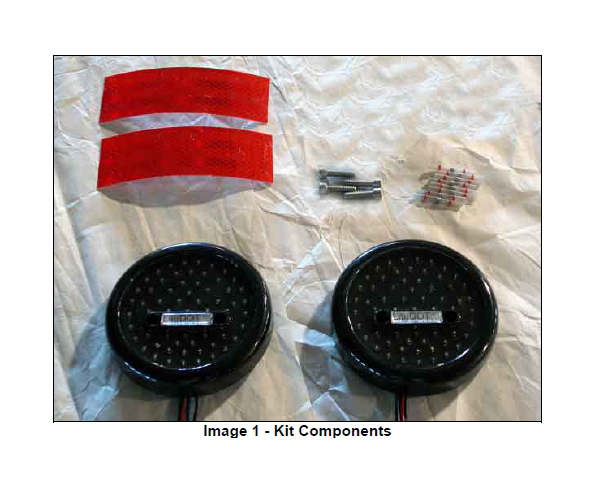
Parts in kit (all quantities 1 unless specified):
• Left taillight
• Right taillight
• Self tapping ¼-20 hex head screw
• (4) ¼-20x1 Socket head cap screws
• (8) Solder Seal shrink connectors (2 spares)
• (2) Reflective tape strips
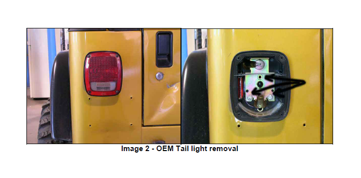
1. Remove OEM Taillights, LiteDOT’s mount to the body with 2 of the three original mounting holes.
a. Remove 4 screws to remove taillight lens.
b. Remove 3 Hex head sheet metal screws to remove taillight from body. (See black arrows in Image 2 on the right)
c. Carefully, extract tail light wiring thru body. There is a connector approximately 12” from the taillight housing, you will disconnect that connector to remove taillights and harness from vehicle. (See Image 3 )
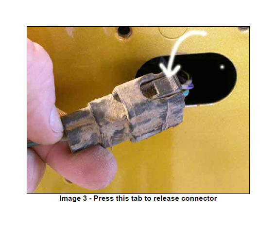
The connector is disconnected by pressing down on the tab highlighted in Image 3 and pulling to separate the connection. Pay special attention to the small locking latch on the connector or terminal damage may occur. It may be necessary to partially remove the plastic inner fender liner to get access to the connection, as it may not have enough free harness to extend thru the opening in the body
2. Remove Factory License Plate mount on TJ Wranglers. This unit will need to be trimmed if it is to be reused See License Plate Mount, Step 12 in this document. Relocation of the license plate is recommended. ORO also offers LitePLATE™ a license plate light assembly that includes a red LED 3rd brake light along with illuminating the license plate.
www.Rockhard4x4.com offers a license plate relocation bracket that will move the license plate to the center of most spare tire carriers.
3. If there is any debris on the body in the area that you are working, a quick wash and rinse of that area will prevent the assembly process from scratching the finish of the Jeep.
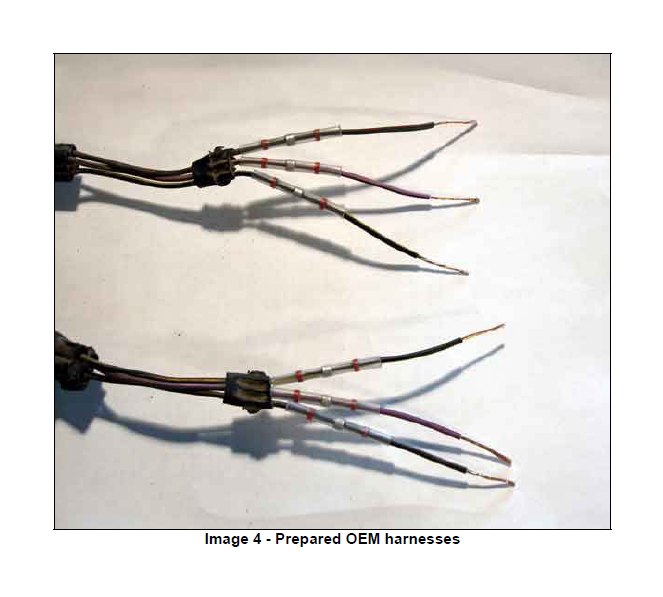
4. Prepare harnesses for connection to LiteDOT’s™
a. Starting at the connector on each harness, measure down approximately 6” and cut the three wires, place OEM taillights off to the side and keep connector ends on your work surface. Place the mounting hardware for the OEM lights inside the taillight housings, as you will be able to reuse these if you decide to remove the LiteDOT’s for whatever reason.
b. Using the sharp knife, trim the plastic harness cover back 2-3”, allowing as much harness length to work with as possible.
c. Place 1 solder seal shrink tube connector over each of the three wires
d. Strip the wire insulation back approximately ¾” on each of the three wires
5. Prepare the LiteDOT’s™ harness for electrical connections
a. There are 4 wires on each LiteDOT™ housing. 1 wire, the BLACK one has a ground tab soldered onto it, this is the ground wire and will be attached to the vehicle body or chassis to ground each assembly. Cut the 3 remaining wires equal in length if they are not delivered that way.
b. Strip approximately ¾” of insulation on each wire, just like on the Jeep harness in step 4d
Wiring color code:
On the LiteDOT's™, the wiring is color coded as follows:
Tail ------------- Brown
Brake/Turn ---- Red
Back-up -------- Blue
Ground --------- Black
To determine if LiteDOT™ is a left or right model, place them side by side as shown in Image 1, with the mounting holes at 4 and 8 o’clock positions, the left taillight will have the 3 side marker LED’s on the left, and the right will have the side marker LED’s on the right.
On a TJ, the wire colors should be as follows:
Left Side:
Tail ------------- Black with Yellow tracer
Brake/Turn ---- Green with Red tracer
Back-up -------- Violet with black tracer
Right Side:
Tail ------------- Black with Yellow tracer
Brake/Turn ---- Brown with Red tracer
Back-up -------- Violet with black tracer
On a YJ, the wire colors should be as follows:
Left Side:
Tail ------------- White
Brake/Turn ---- Green with Black tracer
Back-up -------- White with black tracer
Right Side:
Tail ------------- White
Brake/Turn ---- Green with Black tracer
Back-up -------- White with black tracer
Other models, please test to ensure proper connection to the LiteDOT’s™
6. Harness connections
a. With the wiring color codes as noted above, and with one solder seal shrink connector on each of the three wires on the OEM harnesses, you’re ready to connect to the LiteDOT’s™ harness
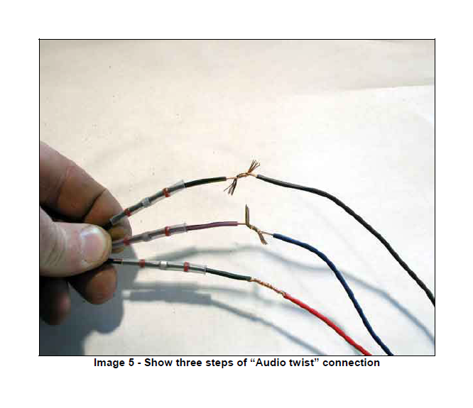
b. Make each connection by placing the two connecting wires intersecting at approximately 90* in the middle of the bare section as shown in Image 5 (top connection.)
c. Proceed by twisting the wires to complete an “audio twist” connection, keep the ends of the wires wrapped as small and tight as possible, this will make the next step easier, as shown in Image 5 (middle and lower connection)
d. Slide the solder seal shrink connector over the connection, centering the silver ring at the center of the shrink tube in the middle of the bare wire splice connection as shown in Image 6.
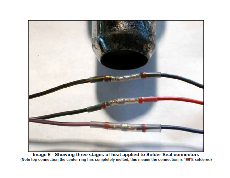
e. Using a heat gun or other high temp heat source (a lighter or other heat source may not be enough to complete the solder and seal shrink process) heat the shrink connector evenly. The clear shrink tube will shrink first and if that’s all the heat available, will keep the wires sealed and connected.
f. If enough heat is available, continued heating will result in the silver solder ring in the center to bubble and melt, resulting in the completion of the connection. Continue this for the remaining wire connections. (See Image 6 to see the three stages of shrinking, starting at the bottom with gentle heat and moving upward with more heat, the top one showing the solder ring melted.)
7. Preparing the mounting holes.
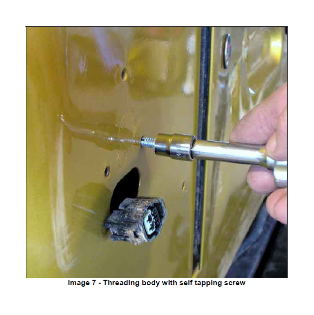
a. The two lower holes on each side will be used to mount the LiteDOT’s™ Locate the ¼-20 hex head self-tapping screw included in the kit. This will be used to prepare each hole for the ¼-20 Socket head cap screw to mount the LiteDOT’s™
b. The area around the screw holes will more than likely be protruding from the body line due to the method of installation at the factory. To get the LiteDOT’s to sit perfectly to the body, it may be necessary to tap the dimples with a hammer to make the area around the two mounting screws to be used flush or indented.
c. Using a 3/8” socket, carefully start the self tapping screw into each of the 4 lower bolt holes, gently threading the screw into the body, allowing it to form the threads as necessary. Run the screw in until it bottoms against the body and then remove. Failure to prepare each hole in this manner could result in the mounting Stainless Socket head cap screw not working properly.
8. LiteDOT’s™ mounting
a. Ensuring that the left and right LiteDOT’s are prepped for the correct sides, you are now ready to mount the LiteDOT’s to the Jeep.
b. The mounting holes are designed to be snug and allow you to start the ¼-20 socket head cap screws and they will be held in place while you assemble the LiteDOT’s™. Start all 4 mounting screws and thread them until the bolts just start to protrude thru the LiteDOT’s™ mounting bosses
c. If the connector is accessible thru the harness hole in the body, plug the harness connectors together, if the connector has fallen in or was left in the wheel well, insert the connector thru the harness hole.
d. Thread the BLACK ground wire with the grounding clip thru the hole as well, ideally you want this to fall all the way to the bottom
e. Place the LiteDOT™ in the approximate position, thread one of the socket head cap screws until it makes contact and starts threading into the body. Continue threading a few turns until it is anchored well. Do not tighten completely as ideally both screws should be tightened evenly.
f. Start second screw, once both are started, work back and forth to tighten both evenly until the LiteDOT™ sits evenly against the body. Do not over tighten! The approximate force for tightening these should be about what you can do with the twist of your wrist, like turning a screwdriver. Using more leverage and creating more force may damage the mounting threads in the body; the result is having to add ¼-20 nuts on the backside of the body to retain the housings.
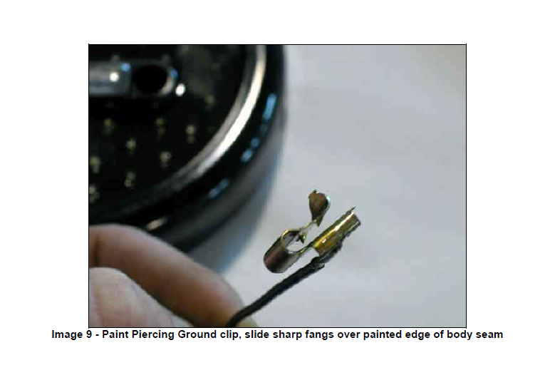
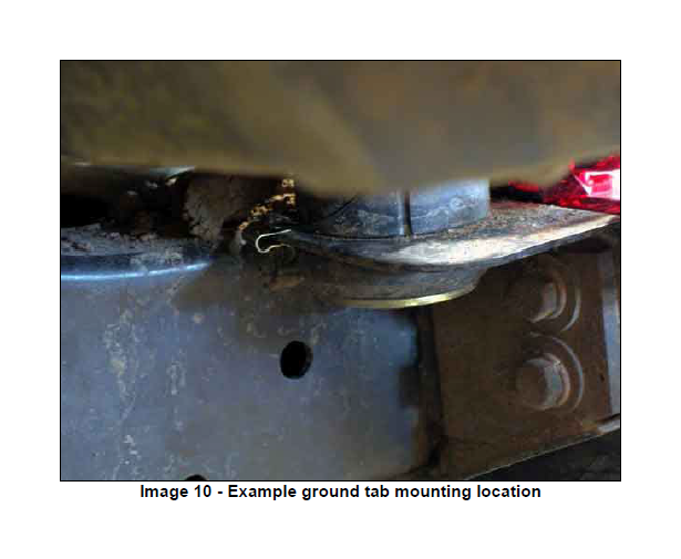
g. Once the LiteDOT’s™ are mounted, and the harness connector is connected, it is now time to ground the assembly to the chassis. The ground wire has a paint piercing grounding tab soldered onto it. (See Image 9) Simply pick the ground location of your choice and slide the tab over the edge so that the piercing fangs grab the surface and retain the clip. There are two common choices for mounting locations, 1 on the body mount bracket near the rear body mounts on each side, directly below the body (See Image 10) or on the inside of the body, on the pinch weld area inside the radius of the tub.
9. Testing LiteDOT’s™ is simple:
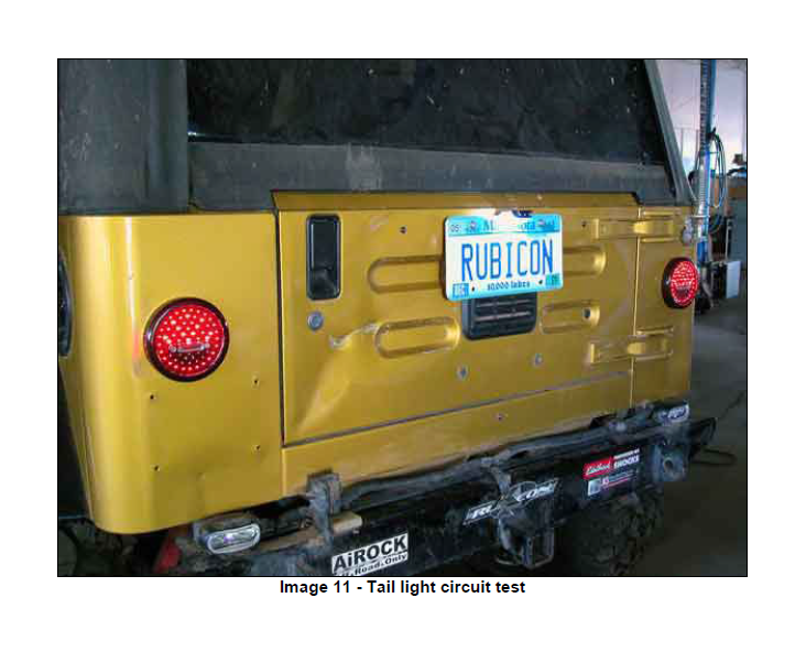
a. Turn on Parking lights, Rear facing red LED’s and side facing red LED’s should light dimly, white reverse indicators should not be lit (See Image 11)
b. Turn Ignition key to ON, engage left turn signal, LEFT LiteDOT™ Red LED’s
should flash from dim to bright and back to dim
Note: Unless you have already addressed the turn signal flasher, it should be flashing
very quickly. This is due to the reduced electrical resistance by removing the
incandescent taillight bulbs. This will be addressed in section 10.
c. Engage right turn signal, RIGHT LiteDOT™ Red LED’s should flash from dim to
bright and back to dim
d. With parking brake firmly set and ensuring that the vehicle will not roll, place
transmission in Reverse, white reverse indicators should light
e. Watch operations as you turn off each of the above to ensure that the operations
are what is expected.
f. Most common issue to troubleshoot, if no LED’s light up, or they do not light up
brightly during Turn signal or brake, then there is most likely a poor ground
connection, moving the ground to a new location, or simply scratching the
connection to help make good connection should solve this issue.
10. Turn signal flashers:
a. On 2001- Current TJ's, the turn signal flasher is located under the plastic cover
on top of the steering column, ahead of the steering wheel. Removing the 3
Phillips head screws from the bottom (You'll see the access holes to insert the
screwdriver) will allow the cover to loosen, there is a small latch on the forward
edge of the cover that requires a small amount of force to release. The flasher is
the black 1" square by approximately 2" long box that is on the right side, just
above the Key. Remove this flasher unit by pulling it away from the steering
wheel, or towards the front of the vehicle. Pay attention to the orientation of the
flasher unit, the terminals will only allow it to go in one way. Take the new flasher
and install it in the same manner. Test by turning on the key and cycling the turn
signal switch and if the turn signals flash slower than previous, as slow as
normal, then the flasher is correct.
b. On pre-2001 TJ's, the flasher is located under the dash, clamped to the steering
column, on the side towards the center of the jeep. To make finding it easier,
remove the knee panel under the dash and its steel backup. Turn the turn signals
on so that the flasher is clicking, then follow the sound and feel for the black box
that is clicking. You can make replacement easier by removing it from it's metal
clip. Disconnect the flasher, replace with new flasher unit. Test turn signals and
stow the flasher unit back in its original mounting position. If the original mounting
clip will not work with the new flasher, simply zip tie the unit into place.
c. On YJ's, the flasher is in the fuse box under the dash. This flasher is a two
terminal flasher and the unit needed is a 3 terminal flasher and a harness. The
two male spades will plug into the fuse box mounting point for the flasher., red
wire will be on the driver side, while the black wire will be on the passenger side.
The red wire will be 12v when the key is on and the terminal may be tested with
a test light to insure that the correct terminal is in the correct socket. The white
wire in the harness must then be attached to a chassis ground. Find a screw
under the dash and attach the ring terminal to it. Test turn signals. If working
properly stow flasher under the dash with zip tie and tie excess harness out of
harms way.
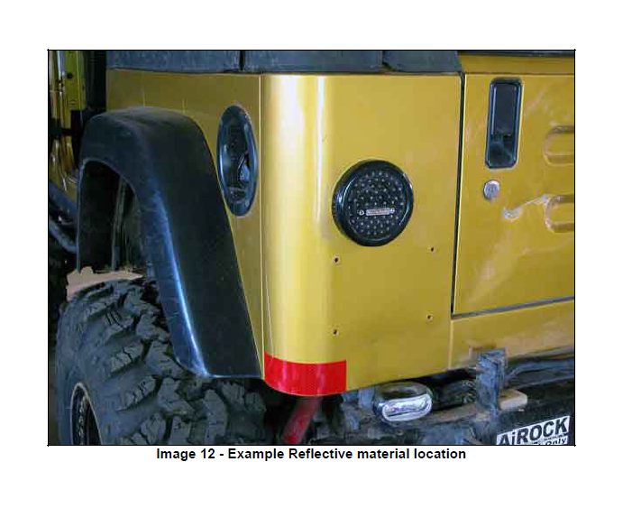
11. Reflective material:
a. Install one of the supplied self-adhesive reflective tape on each rear outer corner
of the vehicle in accordance with local requirements, failure to do so may result in
non-compliance and is the responsibility of the installer. (See Image 12)
12. Decals:
a. Install LiteDOT™ decals in the area between the bolt holes on each lite, as seen
in Image 12
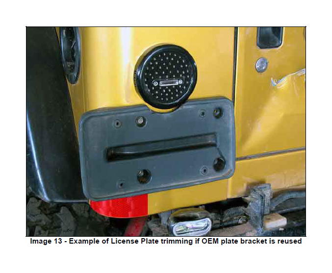
13. License Plate mount:
a. To retain the OEM TJ License plate mount, you will need to trim a small semicircle
on the top edge where the plastic housing will interfere with the LiteDOT™.
This can be easily done with a hacksaw, dremel tool, or die grinder. (See Image 13)
b. The LiteDOT’s™ will not illuminate the License plate adequately, and therefore
ORO recommends installation of the PlateLite™ license plate light assembly.
This will bolt between the license plate and the mount, and will have a small wire
harness to run to the wheel well area to splice into the harness. A simple routing
would be to omit the lower right license plate mounting bolt and fish the harness
thru the bracket and body at that location and splice the wires into the taillight
and ground wires inside the wheel well.
Off Road Only recommends “Lights On for Safety” while the vehicles are in motion.

