FREE 1 to 3-Day Delivery on Orders $149+ Details

How to Install a M.O.R.E. 1 in. Body Lift w/o Shocks on your 1997-2006 Jeep Wrangler TJ

Shop Parts in this Guide
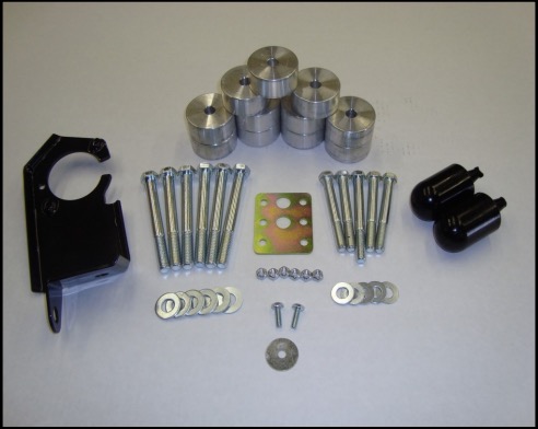
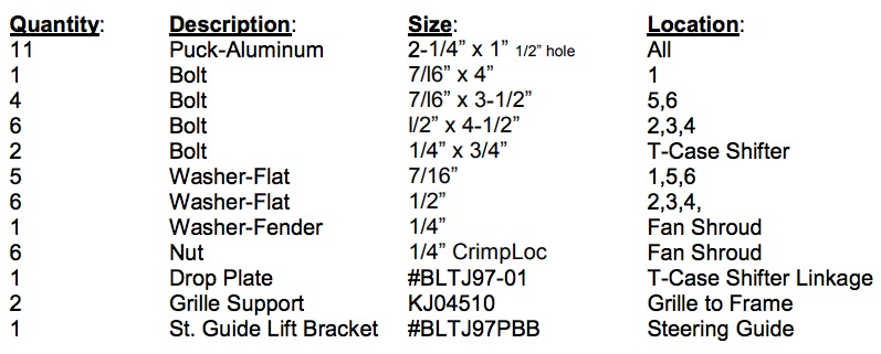
This M.O.R.E.™ One Inch Body Lift Kit fits 1997-2000 Jeep® TJ® Wrangler® vehicles with ether 2.5L or 4.0L engines, with manual or automatic transmissions, with or without air conditioning. This kit has been designed to fit on TJ Wrangler’s that are stock (no suspension lift), or Wrangler’s that have been lifted with aftermarket suspension lift kits up to 4”. M.O.R.E.™ has up-dated this kit from the earlier kits with the necessary hardware to address the following items: Steering Shaft Guide Bracket, Grille Support Blocks, and Transfer Case (T-Case) Shifter Drop Plate. Please read all instructions and our Terms and Policies on page 3 before you begin installing this kit. Familiarize yourself with all components in this kit and the parts of your Jeep that you will be working on. Common hand tools are required and some knowledge of mechanical things are needed. This kit contains the following items:
1. Remove the 4 bolts holding the fan shroud to the radiator.
2. Remove the 4 nuts that hold the fan to the water pump pulley.
3. Remove the shroud and fan.
4. Inside the Jeep on the drivers side, pull the carpet away from the floor pan to expose the 4 bolts that hold the transfer case shift linkage bracket. (This bracket is on the under side of the body and it's purpose is to locate the bellcrank for the linkage.) Remove the 4 bolts and remove the bracket from the under side.
5. Loosen all 11 body mount bolts. Remove the one under the grille. Remove 5 bolts on the driver’s side. (Hint, The hidden mount bolts are between the fuel tank and the upper rear shock mount!).
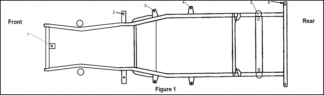
6. Place a stout piece of wood on a floor jack and place the jack between body mount 3 and 4 on the channel portion of the body. Jack up the body just enough to install the 1 inch pucks on top of the factory steel washers/rubber insulators. Place the M.O.R.E.™ pucks in locations 2,3,4,5,6. It is recommended that you use a dab of lock-tight on the new longer bolts. Start the new longer bolts in locations 2,3,4,5,6. Do not tighten at this time. See Figure 1 for locations of body mounts.
6A. If you are replacing the body mounts with our Urethane mounts then the position for these are:
Positions: 1,5, and 6 : MO2288 , M02429 , S10125 See Figure 1
Positions: 2,3, and 4 : M02348 , MO2350 , S10125 See Figure 1
7. Repeat this procedure on the passenger side of the body.
8. Install the last puck under the grille (location 1) and start the longer bolt.
9. Remove the factory rubber grille supports and replace them with the supplied 1” taller urethane grille supports. It is recommended to apply a lubricant to the urethane to help with the install.
10. Now, tighten the new longer body mount bolts. Use your judgment as to how tight to torque the bolts. Do not "crush" the rubber insulators or leave the bolts too loose!
11. Find the 4 holes in the mounting flange on the radiator where the shroud mounted. Measure 1 inch below the factory holes and center punch a mark. Do this as accurately as possible. (The passenger side lower hole will end up in a large existing hole and can not be drilled. (This is what the large fender washer is for.)
12. Drill the center punched marks with a 1/4" drill bit. You may find it easier to use a angle-head drill for this job, however a standard drill can be used.
13. Since the radiator stays in the stock location, and its bolted to the body, it moves up 1 inch with the body lift. The fan shroud must line up with the fan, and it is connected to the engine. The engine stays in the stock location. For the shroud to fit in the new holes you just drilled, the shroud needs to be trimmed slightly to clear the lower radiator hose. You can use a round file, Dremmel® Tool (hi-speed grinder), or what ever you have to perform this job. The shroud is made out of a plastic material that cuts, sands and forms easily, so be careful when grinding or filing. Make sure that the shroud doesn't touch the hose when bolted in place.
14. Install the fan and shroud. Tighten the nuts that hold the fan to the pulley/water pump. Install the factory bolts through the shroud and into the holes you drilled in the mounting flange. Use the CrimpLoc nuts provided. Do not over tighten the nuts/bolts, just a bit past snug will do the trick. The large fender washer is for the lower hole on the passenger side. Place it on the steel side of the mounting flange so the CrimpLoc nut has a surface to grab against.
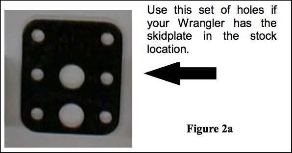
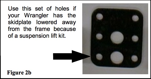
15. The bracket that you removed in Step 4 can now be addressed. Remove the two bolts that hold the swivel ball mount to the bracket. The M.O.R.E.™ drop plate will relocate this swivel ball mount to it’s proper location. Use the bolts that you just removed to attach the drop plate (with-out the swivel ball mount) to the bracket, placing the drop plate with the two large holes down. The swivel ball mount can now be bolted to the drop plate. Where you place it depends on how your Wrangler is set-up. If your Wrangler is stock (no suspension lift) place the swivel ball mount in the upper set of holes. See Figure 2a. If your Wrangler has a suspension lift kit that uses spacers between the frame and skid plate/crossmember, place the swivel ball mount in the lower holes. See Figure 2b.
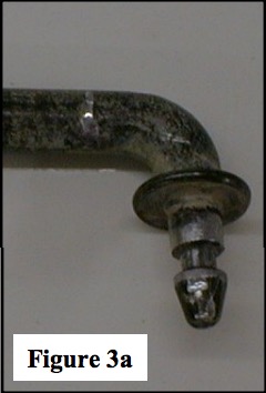
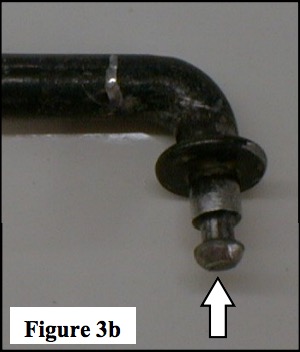
16. The shifter rod that connects the shift lever to the bellcrank needs slight modification. Remove it from the bellcrank by prying the ends out from the plastic grommets. The end that “snaps” into the bellcrank needs to have the point ground off to more of a “nub” then a point. Be careful not to grind too much off the point. See figure 3a & 3b. Figure 4a shows the factory point on the rod. Figure 3b shows how it should look after you have ground the point off, (see arrow).
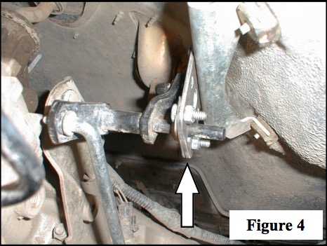
17. Re-Install the bracket to the floor pan. See Figure 4 (this figure shows a Wrangler that has the swivel ball mount in the lower set of holes). Now, you will need to adjust the linkage on the shifter rod between the shift lever and the bellcrank. Find the adjustment bolt on the rod. Make sure the shift lever and the T-case go all the way into low range. The adjustable linkage on the rod will probably need to be adjusted longer. Now, make sure that the T-case and the lever go all the way into high range. This may take some time adjusting it to get it perfect, but it can be done, and is VERY IMPORTANT that it be done so that no damage occurs to the T-case.
18. If your Wrangler is equipped with a automatic transmission, no modifications are necessary. It is cable operated from the shifter to the transmission and has plenty of slack for the 1" body lift.
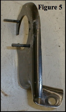
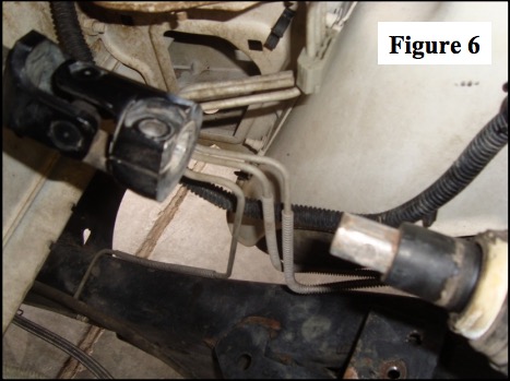
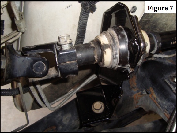
19. The factory steering guide bracket now gets replaced with the M.O.R.E.™ raised steering guide bracket. This guide bracket is located in the engine compartment, between the steering column and the steering box See Figure 5. Remove the bolts that attach it to the frame and steering shaft bearing. Remove the bolt that clamps the upper shaft to the lower shaft and separate the shafts See Figure 6. Now remove the bracket from the lower shaft and replace with the supplied raised bracket using the original hardware See Figure 7.
20. Go back and re-check all of your work. Make sure that all the bolts are tight and nothing has been left "undone".
Re-check the body bolts, T-case linkage adjustment and steering shaft guide bracket bolts after 4-Wheeling and every few months. If you have any questions or comments, please call. Thank you for purchasing
this product from M.O.R.E.™.
TERMS-POLICIES:
RETURNS: No returns will be accepted without prior permission from M.O.R.E.™ LLC. After you receive a Return Goods Authorization (RGA) number, merchandise must be returned prepaid and insured. A claim must be made with in 30 days from receipt of merchandise. The original invoice or a copy with the RGA number written on must accompany all returns. A 20% restocking fee will be charged on all parts returned for credit or refund unless merchandise is proven to be defective or was shipped wrong by M.O.R.E.™ LLC. No merchandise will be issued credit or refund if it has been installed, modified, used in any way or is in unsalable condition.
WARRANTY: All merchandise is warranted to be free from defects in materials and workmanship prior to installation. Any alteration or improper use will void this warranty. Because all parts we sell are intended for use in heavy-duty applications it is not possible to warrantee or guarantee the performance of any items. M.O.R.E.™ LLC. products and the products manufactured by others, which we sell may be subject to an infinite variety of conditions due to the manner in which they are used, serviced and/or installed. Purchasers and users of such products rely upon their own judgment as to the suitable use selection, service and installation of such products.
PRODUCT DISCLAIMER: Modification of your vehicle to enhance performance with parts sold by M.O.R.E.™ Inc. may create a dangerous condition which could cause serious bodily injury, and the buyer hereby expressly assumes all risks associated with any such modifications. All parts sold by M.O.R.E.™ LLC. are for racing or off road use only. Mountain Off Road Enterprises LLC. will not accept responsibility for personal injury or property damage arising from the failure of any parts manufactured or sold by M.O.R.E.™ LLC.
Specifications are subject to change without notice.
Jeep® , TJ® , Wrangler® , are registered trademarks of DaimlerChrysler . M.0.R.E.™ is a trademark used by Mountain Off Road Enterprises, LLC. The M.O.R.E.™ logo and these instructions are copyright© , 2009.
Now Go Jeepin!