 FREE 1 to 3-Day Delivery on Orders $149+ Details

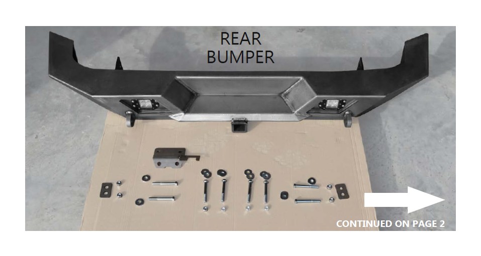
How to Install LoD Offroad Destroyer Full-Width Rear Bumper w/ Tire Carrier - Bare Steel (07-18 Wrangler JK) on your Jeep Wrangler
Installation Time
2 hours
Tools Required
- 5/16” socket
- 7/16” socket
- 5/8” wrench
- 11/16” wrench
- 3/4 “ wrench
- 1 1/2 socket**
- ratchet
- ratchet Extension
- 5/16” wrench
- 7/16” wrench
- drill with 1/2” drill bit
- grease
STEP 2 : Before beginning the installation, there will be 8 locations (some are embossed/marked into the surface) that require drilling through the cross members.
*Use a 1/2” drill bit for drilling these.*
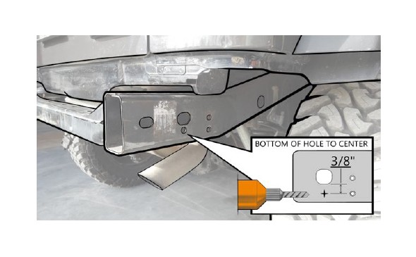
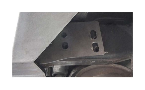
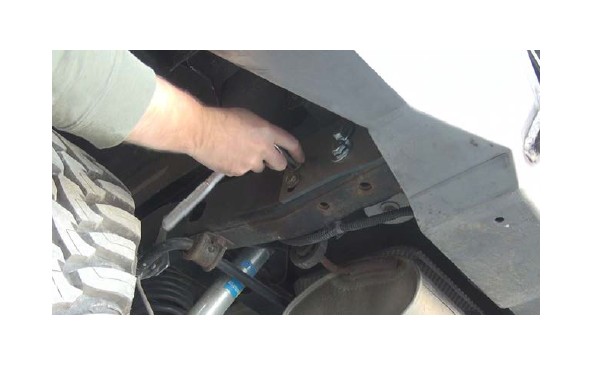
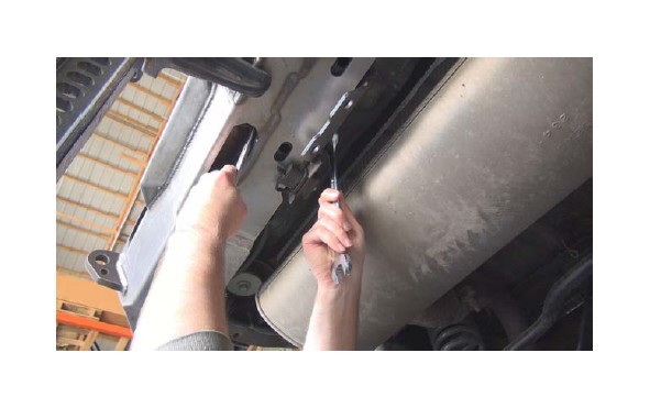
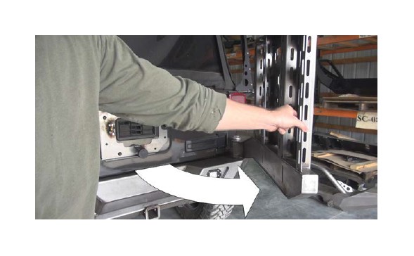
STEP 3 : Each side of the frame will have a hole (shown here) that will need to be marked and drilled with a 1/2” drill bit.
This hole can be drilled with the bumper on the vehicle.
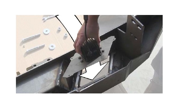
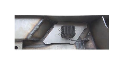
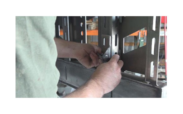
STEP 4 : After attaching the lights, place the bezel into the frame and attach with the provided #8 self-tapping screws.
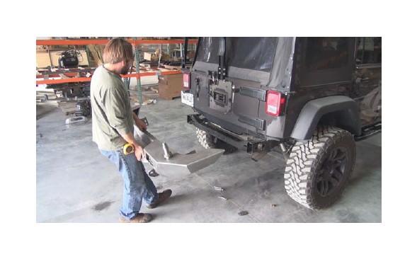
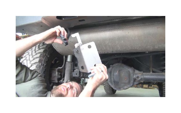
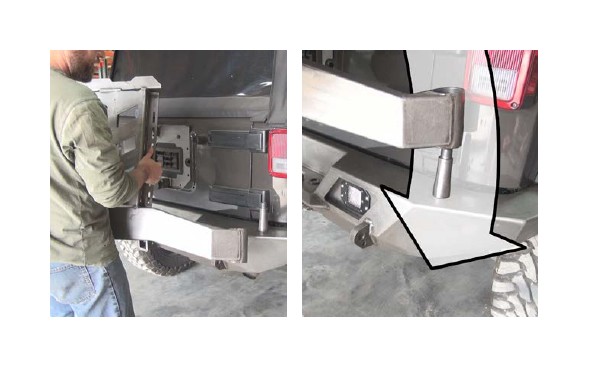
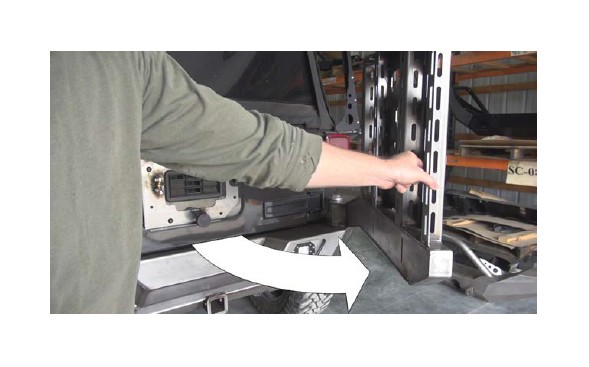
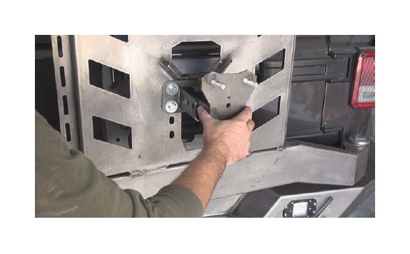
STEP 5 : Carefully pick up the bumper and slowly center it, then move towards the Jeep.
Take care to avoid damaging the body with the bumper corners.
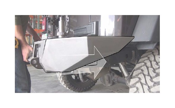
STEP 6 : Slide the bumper forward onto the frame once the body of the bumper is aligned with the body of the vehicle.
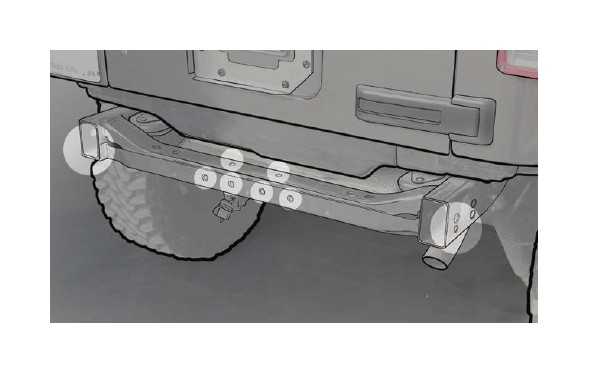
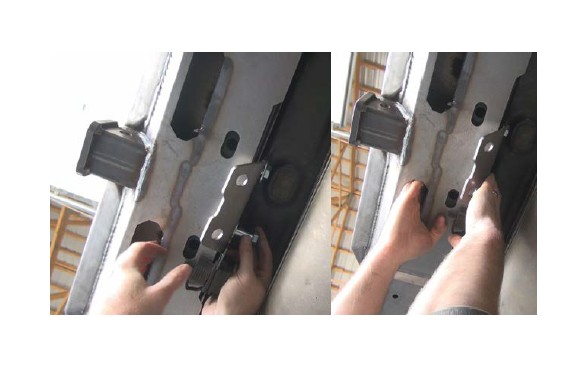
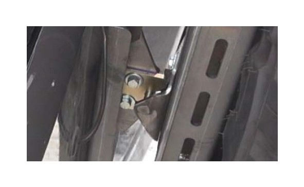
STEP 7 : Do not let go of the bumper, as it may fall unsupported. While keeping pressure on the bumper, check that the two stock holes (circled) are lining up with the slotted holes in the bumper
STEP 8 : Insert the two stock frame bolts, do not tighten them all the way.
STEP 9 : You may now let go of the bumper, the stock bolts will prevent it from falling off.
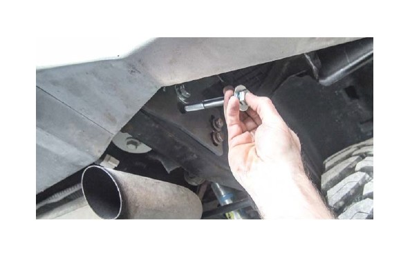
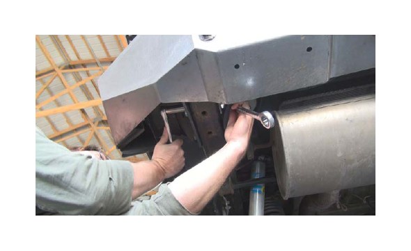
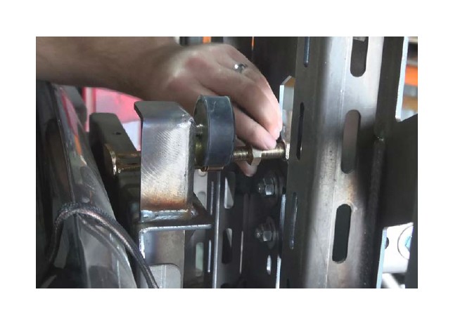
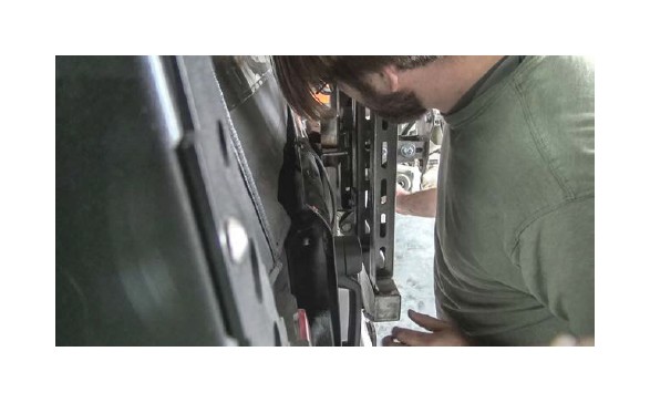
STEP 10 : Insert the 4” long bolts into the opening (you may have to flip the bolt in the picture). The bottom hole should have been drilled by this point to provide a space for the bottom 4” bolt.
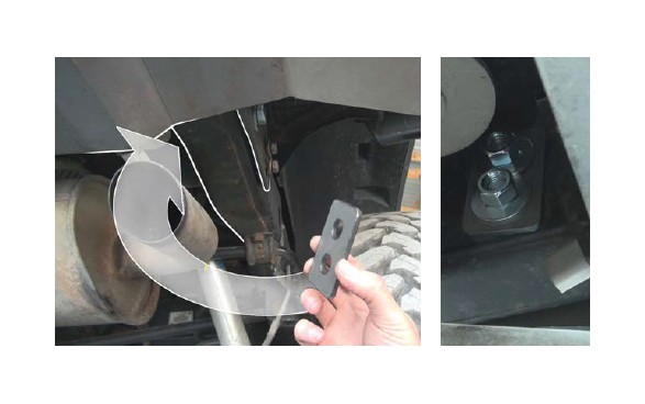
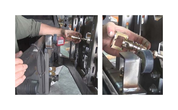
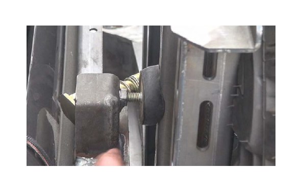
STEP 11 : After inserting the bolts, attach the frame backing plate onto the studs, then attach the nuts and washers.
The washers will overlap (pictured on the right). This is fine, they will be squished down when the bolts are tightened. If you are so inclined, you can trim the washers so they do not overlap.
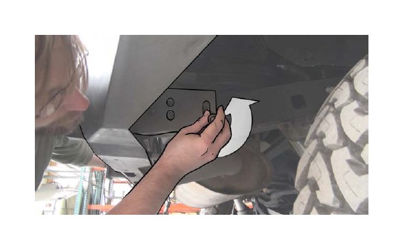
STEP 12 : Attach the trailer plug to the provided safety chain plate.
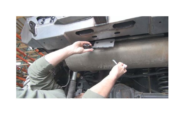
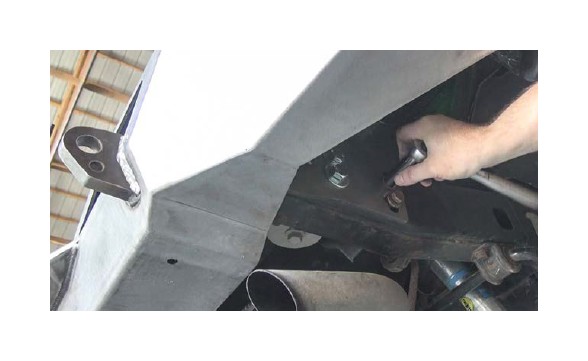
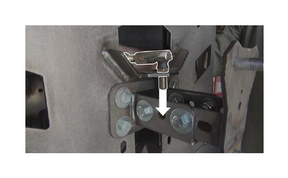
STEP 13 : Locate the two horizontal bolts and align with the holes on the safety chain plate. Face the bent corner towards the front of the vehicle.
STEP 14 : Insert the bolts, and loosely thread on the nuts and bolts using the access hole cutouts.
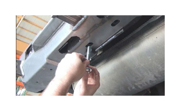
STEP 15 : Insert two 1/2”x4” bolts into the two vertical holes that were drilled out earlier. Place the corresponding size nuts on the other side.
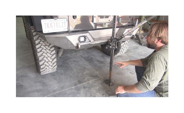
STEP 16 : At this point, we will be leveling* the bumper.
*Having a level bumper is crucial to the proper functioning of the carrier.*
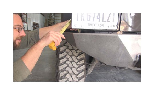
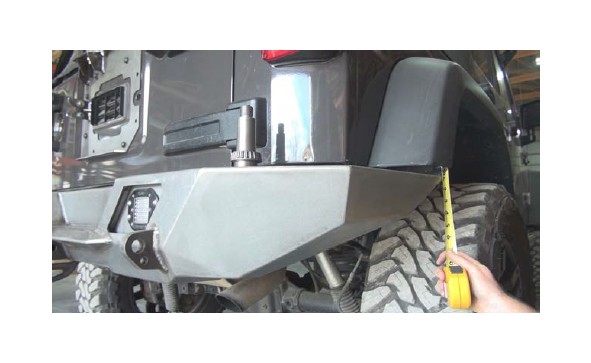
STEP 17 : Measure the gap between the bumper and Jeep body on both sides, the measurements should be equal.
STEP 18 : Tighten the stock bolts, one at a time on each side, one side at a time.
STEP 19 : As you go back and forth tightening the bolts, keep checking your gap measurements to make sure the bumper has not shifted.
STEP 20 : After tightening one bolt on the passenger/driver side, check your measurements then repeat in the corresponding bolt on the opposite side of the car.
STEP 21 : Use a wrench to reach and keep the nuts in place while you tighten the bolts.
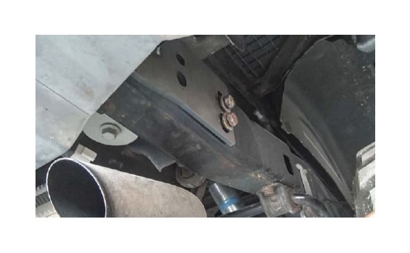
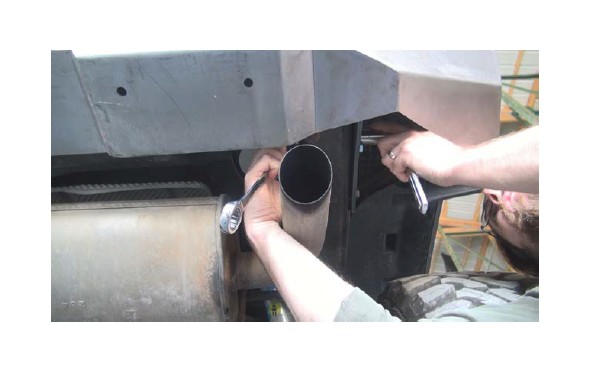
STEP 22 : Using the access holes and the 3/4” wrenches, tighten the bolts that hold the safety chain plate to the crossmember.
STEP 23 : Check that all of the bolts securing the bumper to the Jeep are tight now.
STEP 24 : Measure the middle and corner gaps between the Jeep body and the bumper to make sure it has not changed.
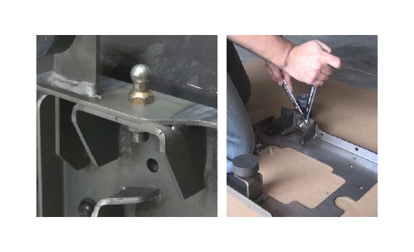
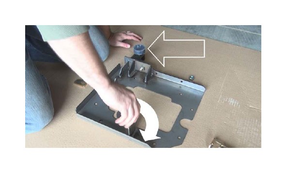
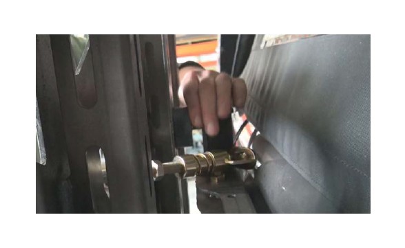
STEP 25 : Install the ball stud for the quick latch system, you may apply Locktite to the threads.
Using a 5/8” wrench on top and a 3/4” wrench on the bottom, tighten it down.
STEP 26 : Screw in the two rubber bumpers that came in the installation kit.
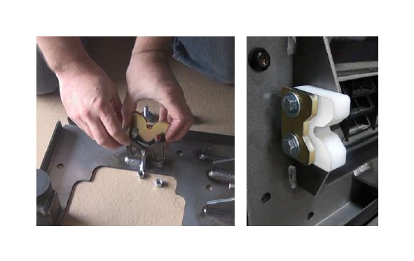
STEP 27 : Attach the striker plate/washer with the TWO 5/16” bolts provided in the install kit.
*With this latch, final adjustment should be done with the carrier loaded*
The striker plate is polymer, sandwiched with a metal “washer” plate to distribute force.
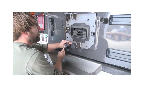
STEP 28 : Attach the door plate to the stock bolt holes on the Jeep door with the 8 stock bolts.
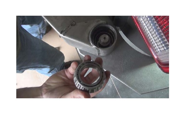
STEP 29 : At this point you should thoroughly pack BOTH of the wheel bearings with grease.
STEP 30 : Place bearing LM29749 onto the spindle, tapered side up. It should slide down all the way and spin freely. If not, you are using the wrong bearing.
Make SURE to check the bearing number to make sure you have the correct one. Mixing up the bearings can damage the spindle.
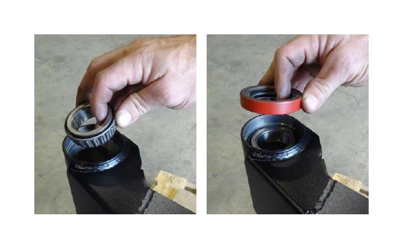
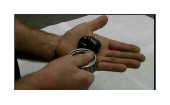
STEP 31 : Flip the carrier arm upside down, so the arm is horizontally on top. Take the bearing from Step 30 and place it, taper down, into the opening.
Next, place the bearing seal on top of the bearing. The text on the seal must face out.
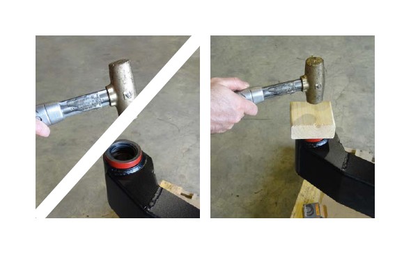
STEP 32 : Do NOT use a hammer directly on the seal or you WILL deform/ damage it or the carrier. Tap it down
Use something soft like a block of wood to spread out the force as you lightly tap the seal into place, otherwise you will void your warranty.
STEP 33 : Under no circumstances should you force the bearings onto the spindle. If you find the bearing doesn’t fit, polish/sand the spindle very slightly. Be careful to not take off too much material.
STEP 34 : Place the carrier arm down onto the spindle. Make sure to keep the welded tube portion perpendicular to the spindle.
STEP 35 : Place the top LM48548 bearing (greased in step 33) into the spindle, with the taper facing down.
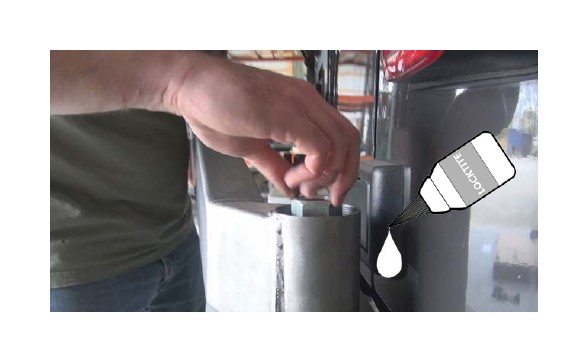
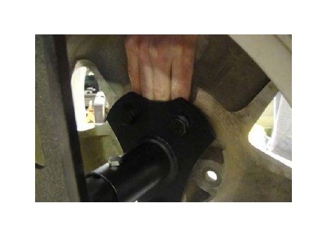
STEP 36 : Place a washer onto the spindle, then the 1” spindle nut on top. Be sure to add Locktite to the spindle threads before you tighten the nut completely.
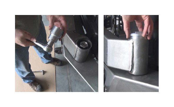
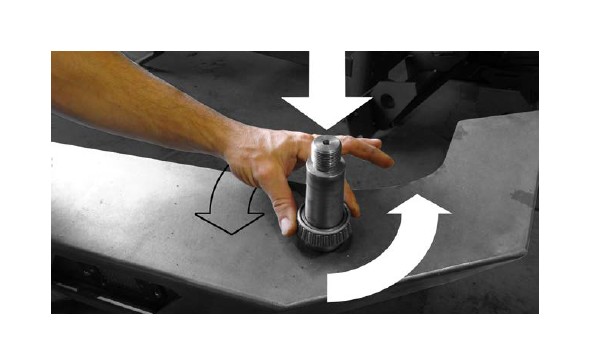
STEP 37 : Tighten down the nut with a 1-1/2” socket
Then add the top aluminum cap, and also tighten that with the 1-1/2” socket.
STEP 38 : Test the swing arm operation by moving the door back and forth. The motion should be smooth and unobstructed.
STEP 39 : Attach the latch alignment guide to the back of the carrier with the provided 5/16” hardware. Attach it loosely so that it can be shifted slightly.
If you plan on loading the carrier, (we used a tire) it will shift down slightly, so you may have to re-adjust it.
STEP 40 : Install the quick latch by inserting the threaded parts through the mount holes and attaching with the washers and 1/2”-20 hex nuts on the other side.
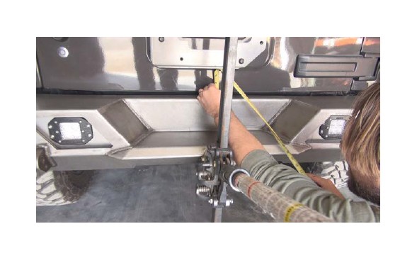
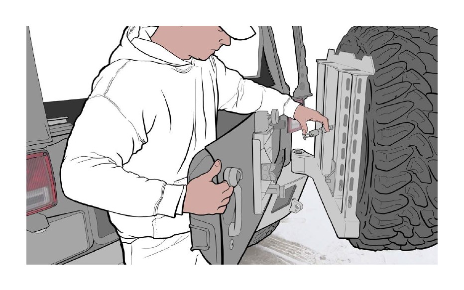
STEP 41 : Standing behind the Jeep door, grab the quicklatch with your left hand and slowly move the door until it is close enough for the latch to be operated.
Press down on the plunger with your thumb and swing the latch down onto the mount stud to attach the latch to the mount stud on the door plate.
ANTI-RATTLE SYSTEM:
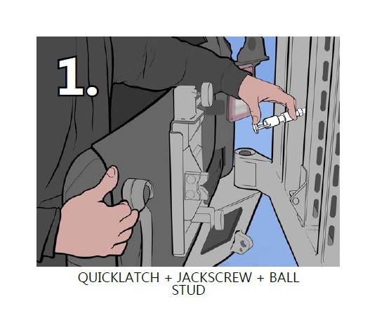
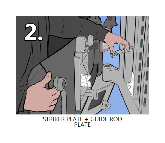
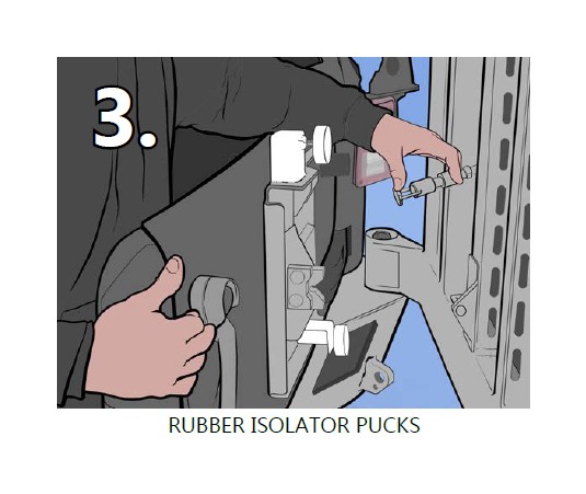
The three components of the system pictured here need to be adjusted in conjunction for the tire carrier to work properly.
They must be adjusted in the order listed for the best fit and function.
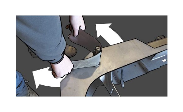
STEP 42: With tailgate and carrier open, stand as illustrated and join the two using the quick release thumb latch.
STEP 43 : **The carrier and tailgate must be closed for this step.**
Adjust the distance between the carrier arm and the Jeep tailgate by adjusting the jack screw latch system. This will make sure the carrier arm and bumper face are parallel (shown in Step 44)
STEP 44 : In order for the carrier to close and stay shut properly, the carrier arm face and bumper face must be oriented perpendicular to the side (profile) view.
Use the jack screw to adjust (illustrated in Step 43).
** Do NOT try to line the faces up, they are not meant to be on the same plane, just parallel, meaning the carrier arm is not swung out nor in too far**
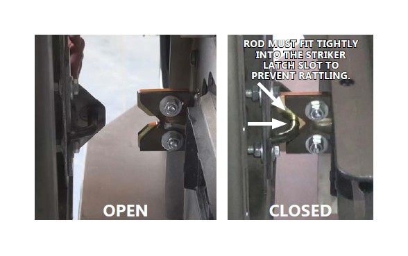
STEP 45 : With the rear tailgate and carrier linked, open the tailgate so there is a 7 - 10” gap, now you are ready to adjust the striker plate/guide rod.
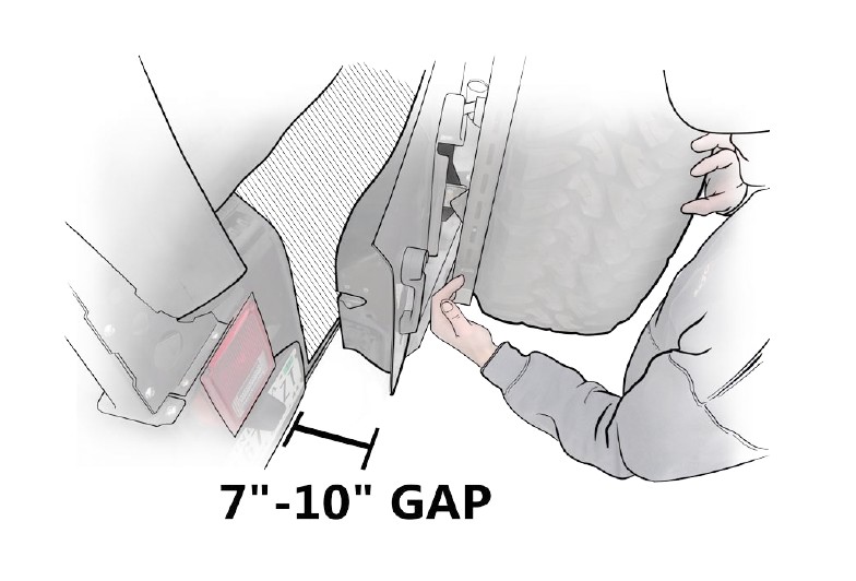
STEP 45 : With the tailgate still open 7 - 10” adjust the striker latch and guide rod so they touch, as shown here.
STEP 46 : Now carefully close the door, taking care to not slam it shut. It should shut and latch smoothly, engaging fully and slightly wedging into the slot.
Pressure on the rod is REQUIRED when engaged into the slot in the closed position.
STEP 47 : After the quicklatch and striker plate are adjusted, open your carrier 7 - 10 inches again, and unscrew the rubber pucks so they touch the back face of the carrier.
*when closed the isolator pucks must be squished, as seen below*
STEP 48 : The pucks must squish slightly when the carrier is shut, with enough pressure to keep a loaded carrier from rattling.
When closed they (the pucks) should look like this.
STEP 49 : Test the door, making sure it does not rattle when closed. If it does, repeat steps 42 - 48.
STEP 50 : Now attach both of the tire mounts to the carrier body. Use an 11/16“ wrench on the nuts and 5/8“ wrench on the bolts.
After this step, you should be ready to attach a spare tire or equipment.
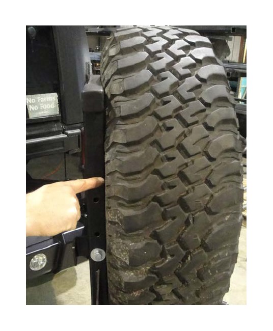
STEP 51 : The spare tire mount is designed to “pull” the tire tight against the carrier using the lug studs.
There can be a gap between the wheel and mount when mounted. Simply adjust the mount in or out until the tire rubber touches the carrier before the rear face of the wheel touches the plate with the lug studs.
POST-INSTALL : Troubleshooting
If you encounter any trouble or rattling, please review the following information, as it may be helpful in understanding the proper function and setup of the tire carrier combo.
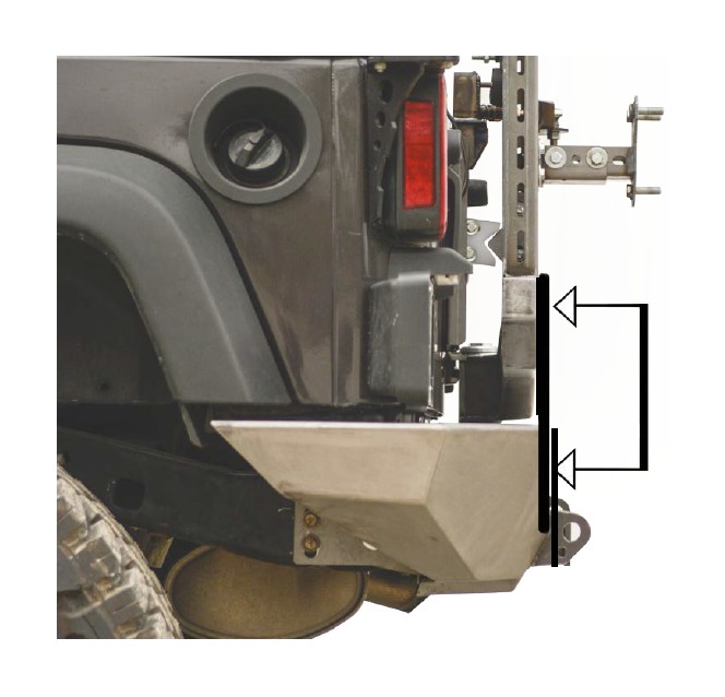
STEP 52 : If you plan on loading the carrier with weight, (we used a 35” tire) plate A will shift down slightly, causing it to catch on B*. To stop any interference, you will have to re-adjust B to be centered with A again after the carrier is loaded with its full weight you plan to carry.
*reference diagram in troubleshooting section at end*
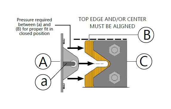
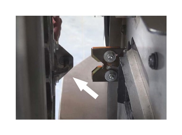
STEP 53 : Here is a closer look at the striker mechanism. The alignment plate rod (a) should be centered to the cutout in (B). The top edges of (B) and (C) should line up.
Offset (B) towards (A) slightly and tighten it down. This way there will be a slight pressure on B and it will prevent A from rattling (shown with black arrows)
STEP 54 : When the door is closed, the alignment plate should fit together smoothly. If it does not, adjust the height of (B)* slightly.
*references Step 53
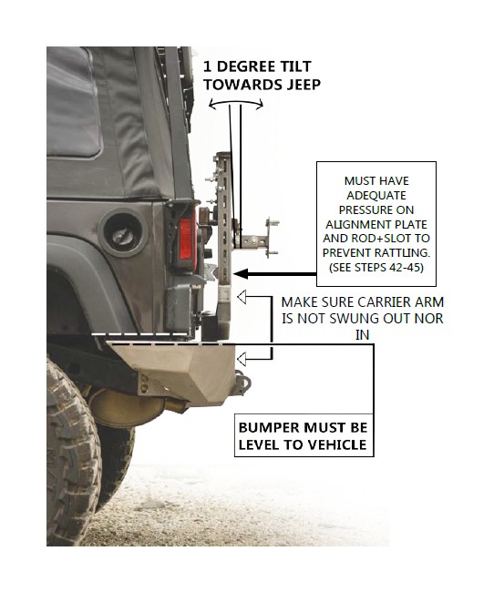
STEP 55 : This diagram illustrates final bumper fitment with the carrier shut. The top of the bumper is level to the body of the Jeep. The carrier is tilted slightly towards the vehicle.
TIP 1 : If you find that the carrier does not shut properly, MAKE SURE you check the level of the bumper to the vehicle body lines, as it may have shifted during installation.
TIP 2 : If you find that the rubber bumpers are not long enough, again, check your mounting bolts, level of the bumper, striker plate, and jack screw distance.
That’s it, the install should now be complete!
