 FREE 1 to 3-Day Delivery on Orders $149+ Details

How to Install KC HiLiTES 32 in. Gravity Pro6 LED Light Bar - Spot/Spread Combo on your 87-18 Jeep Wrangler YJ, TJ, JK & JL

Shop Parts in this Guide
- KC HiLiTES 32-Inch Gravity Pro6 LED Light Bar; Spot/Spread Combo Beam (Universal; Some Adaptation May Be Required)
- KC HiLiTES 50-Inch Gravity Pro6 LED Light Bar; Spot/Spread Combo Beam (Universal; Some Adaptation May Be Required)
- KC HiLiTES 50-Inch Gravity Pro6 LED Light Bar with Windshield Mounting Brackets (07-18 Jeep Wrangler JK)
APPLICATION GUIDE
The Pro6 LED Light Bar is the industry’s first expandable and configurable LED lighting system. This instruction manual will guide you through proper installation of your Pro6 LED Light bar to allow you to take full advantage of all its features.
General Sizing
The height of the Pro6 LED Light Bar is 6” (top to bottom) with a depth of 3” (center mount to back of light). Due to the dynamic nature of the adjustable Infinity Rings, the width of the light bar changes based on the configuration. When considering the application, please reference the size range in the table below.
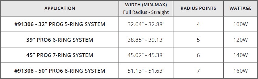
APPLICATION TABLE
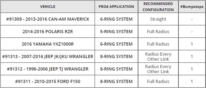
Vehicle Specific Applications
The following vehicle specific kits were developed with a pre-configured Pro6 - Complete with harness, switch kit, and vehicle-specific mounting brackets for the ultimate, direct bolt-on, turn-key solution. Please find the recommended configuration for your vehicle specific application.
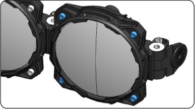
INTRODUCTION
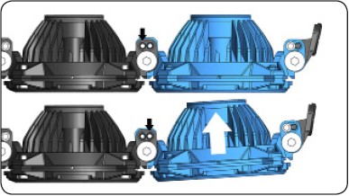
The Pro6 LED Light Bar is driven by an interchangeable G6 Optical Insert. Encapsulated in our race-proven Infinity Ring System. The modular linking design allows straight, partial-radius and full-radius LED Light Bar configurations to suit the needs of a specific performance application. A race-tested bumpstop is included that provides additional support and vibration dampening under extreme off-road conditions in 6-Ring and above Pro6 products.

PRO6 INSTALLATION - MOUNTING TO VEHICLE
1. Remove End MountHardware
Remove the M8 Mounting hardware from End Mounts on both sides of the bar. This will allow for easier installation on fixed mounting applications.
2. Loosen End Mount Adjustment Screws
Loosen the M6 Socket-cap Adjustment Screws from End Mounts on both sides of the bar to allow alignment and self-centering.
3. Mounting the Pro6 Light Bar to Vehicle
Safely install the Pro6 by aligning the M8 Hardware on the End Mounts to the Vehicle Mounts. (The ambidextrous design of the mounts allow for the threads to be installed in either direction.)
4. Level & Final Tightening Down
Set the final level and pitch of the Pro6: 1) Tighten the M8 Horizontal Mounting Hardware, allowing the Pro6 to center itself. Then, 2) Tighten the M6 End Mount Adjustment Screws to lock light into position.
PRO6 INSTALLATION - BUMP-STOP
INSTALLATION & ADJUSTMENT
1. Positioning the Bump-stop Assembly
The Bump-stops are anchored on the pivot points between the Pro6 Infinity Ring(s). Make sure to select pivot point that will not interfere any moving parts on the vehicle.
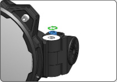
2. Removing Hardware
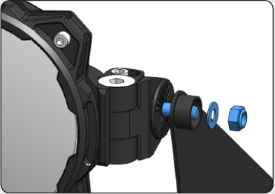
Once a pivot point has been selected, loosen the M6 adjustment screw (to reduce tension) and remove (only) the custom stainless steel M10 Countersunk Shoulder Bolt.
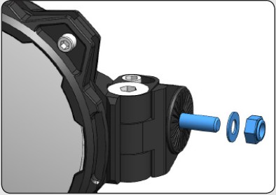
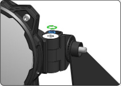
3. Attaching Bump-stop to the Pro6 LED Light Bar
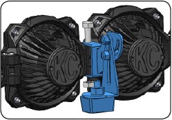
Begin by re-tightening the M6 adjustment screw. Using the supplied M10 shoulder bolt and nyloc nut, firmly attach the Bump-stop Assembly to the Pro6 LED Light Bar.
4. Position Bump-stop Armature
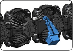
Adjust the position angle of the Bump-stop Armature so that the face of the bushing is mated as flat as possible to the stable surface. The bushing itself can also be loosened and adjusted to help achieve a desired angle.
5. Pre-Load Bar & Final Tightening
Before the final tightening down of the Bump-stop armature, make sure to pre-load the bar to ensure tension is already achieved for maximum stability and vibration dampening. This is accomplished by lifting the bar away from the surface before tightening down the armature.
PRO6 CONFIGURATIONS
STRAIGHT | SEMI-RADIUS | FULL RADIUS
A unique feature of the Pro6 is the ability to go from a Straight configuration, to a full-radius configuration. The Infinity Ring system allows for radius adjustments at every link - depending on the application, the Pro6 can offer a multitude of configurations to provide all customization that one may need for their particular requirements.
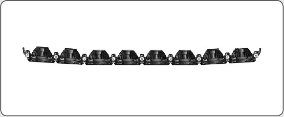
Straight
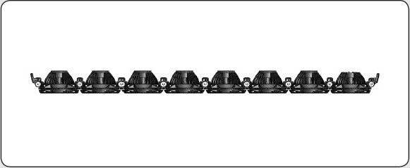
The Pro6 LED Light Bar System comes standard straight.
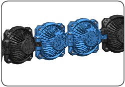
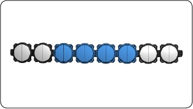
Semi-Radius
For specific application, a partial radius can be configured. Here there is only 2-radiused points between 2nd/3rd and 6th/7th Infinity Rings.
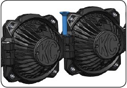
Full Radius
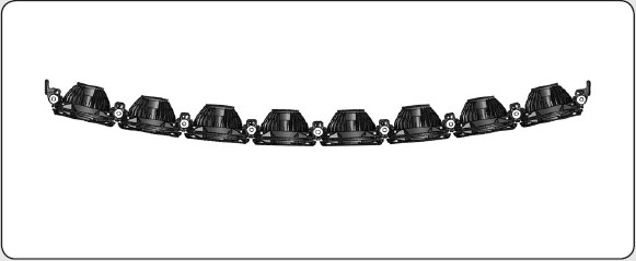
All the radius points have been configured giving the Pro6 LED Light Bar a full radius.
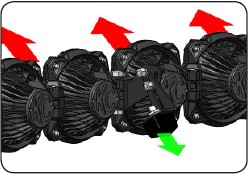
ADVANCED PRO6 ADJUSTMENTS
SETTING THE RADIUS CONFIGURATION
1. Preparing to set radius
Before configuring the Pro6 LED Light Bar, first reference the Application Table for the desired set-up, to identify the radius point(s) needing for adjustment.
2. Remove Adjustment Screw
Remove the M6 socket-cap adjustment screw and loosen the M10 Countersunk Shoulder bolts to allow repositioning the linked Infinity Ring assemblies easier.
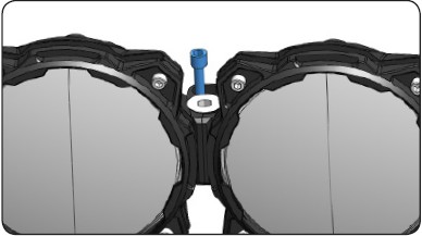
3. Align Radius Position Holes
To set the Infinity Rings into a radius position, adjust the ring assembly so that the adjacent position holes are aligned.
Note: The previous straight position holes will no longer be in alignment.
4. Set Adjustment Screw
Re-apply the M6 socket-cap adjustment screw(s) into the newly aligned radius position holes and re-tighten the M10 Countersunk Shoulder bolts.
Note: Make sure to hand-tighten the screws before using tools to prevent cross threading, and avoid over-tightening the M6 hardware to prevent stripping.
ADVANCED PRO6 ADJUSTMENTS
G6 OPTICAL INSERT REMOVAL & CLOCKING
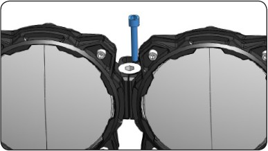
1. Dis-assemble Infinity Ring
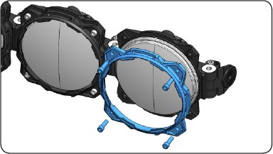
To remove or rotate G6 Optical Insert, loosen and remove the four M6 Socket Allen-Cap Screws and remove Front Ring.
Caution: Once loosened, the G6 Optical Insert could fall out and sustain or cause damage to light or vehicle.
2. G6 Insert Removal/Replace

After the front ring has been removed, to remove or replace the G6 Optical Insert - simply locate the connection to the harness, and unplug the connector.
3. G6 Insert Clocking
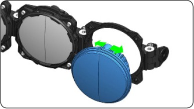
The G6 Optical Inserts have an indexing tab - that when used in conjunction with the Infinity Ring System, it allows the G6 Inserts to be clocked in 22.5° increments.
Note: If the indexing tab on the G6 Insert is not seated with the Infinity Rings correctly, the rings will not fasten together.
4. Re-assemble Infinity Rings
After the desired adjustment is in place, re-assemble the front ring with the M6 Socket Allen- Cap Screws.
