 FREE 1 to 3-Day Delivery on Orders $149+ Details

How to Install a K&N 57 Series FIPK Performance Cold Air Intake on your 1997-2006 Jeep Wrangler TJ
Installation Time
1 hours
Tools Required
- Flat blade screwdriver
- Pair of dikesRatchet
- 7/16" deep socket
- 10mm socket
- 10mm wrench
- 4mm allen wrench
- 5mm allen wrench
- Drill
- 3/4 Drill Bit

Shop Parts in this Guide
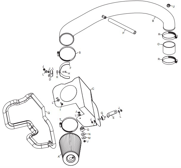
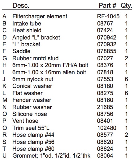
PARTS LIST:
NOTE: FAILURE TO FOLLOW INSTALLATION INSTRUCTIONS AND NOT USING THE PROVIDED HARDWARE MAY DAMAGE THE INTAKE TUBE, THROTTLE BODY AND ENGINE.
TO START:
1. Turn the ignition OFF and disconnect the vehicle's negative battery cable.
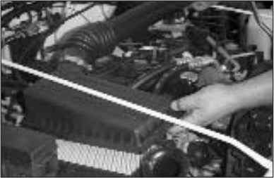
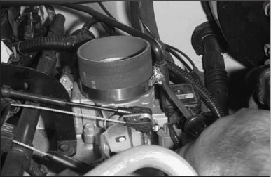
2. Detach the crankcase vent hose from the stock intake tube.
3. Loosen the hose clamp on the intake tube at the throttle body.
3a. On vehicles equipped with temp sensors, depress the temperature sensor electrical connection locking tab, and then pull on the connector to disconnect the connection.
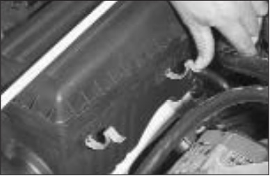
4. Release the 5 over center clips that retain the airbox top to airbox base.
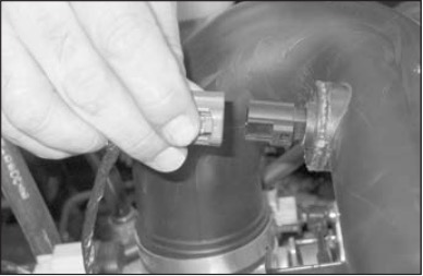
5. On vehicles equipped with temp sensors, lift the temperature sensor-locking tab while twisting the sensor counter clockwise to remove the sensor from the tube.
NOTE: The temperature sensor is fragile, handle with care.
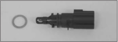
5a. Remove the sealing o-ring from the temperature sensor as shown.
6. Detach the intake tube from the throttle body and remove the entire upper air intake assembly.
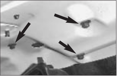
7. Loosen and remove the 3 nuts that retain the airbox base to the inner fender apron.
Note: These are accessed from the underside of the fender.
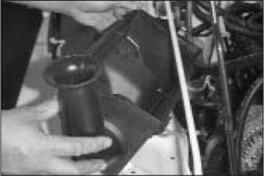
8. Remove the airbox base.
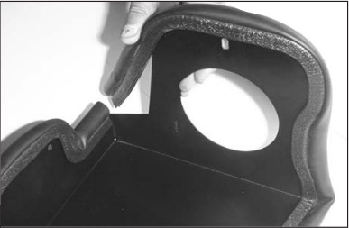
9. Install trim seal onto the heat shield. Note: Some cutting and trimming will be necessary to achieve best fit.
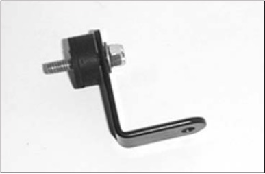
10. Attach a rubber mounted stud provided to the "L" bracket using the hardware provided.
Note: Do not tighten completely at this time.
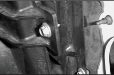
11. Loosen and remove the upper radiator shroud retaining bolt.
12.Install the "L" bracket using the bolt removed in the previous step.
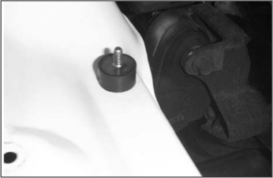
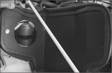
13. Install the second rubber mounted stud into the lower airbox mounting point using the hardware provided.
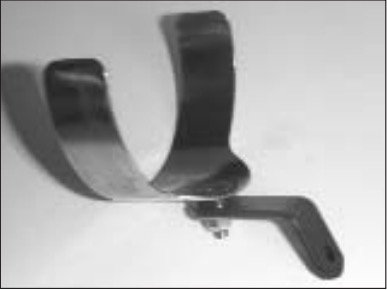
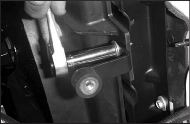
14. Assemble the saddle and "L" bracket using the hardware provided.
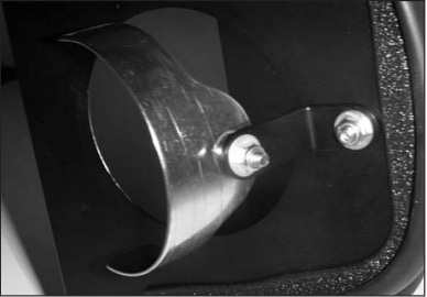
15. Attach the saddle bracket assembly to the heat shield using the hardware provided.
Note: Do not tighten completely at this time.
16. Install the heat shield assembly.
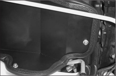
17. Secure the heat shield to the rubber mounted studs using the hardware provided.
18. Attach the silicone hose to the throttle body using a hose clamp provided.
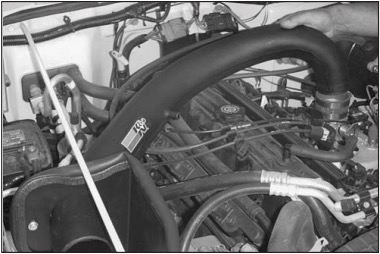
19. Install the K&N intake tube.
19a. Position the temperature sensor electrical connector next to the K&N intake tube for the best fit, then mark the location for drilled.
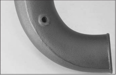
19b. Remove the K&N intake tube from the vehicle and drill a 3/4” hole at the positioned marked in step #19a. Next install the provided grommet into the drilled hole.
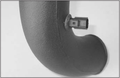
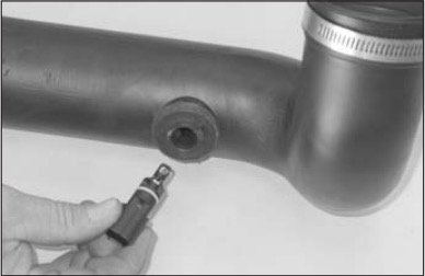
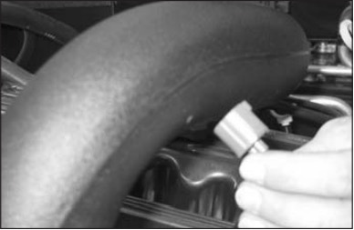
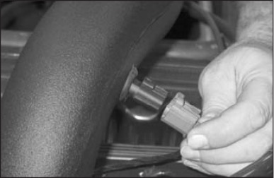
19c. Install the temperature sensor into the grommet as shown.
NOTE: The temperature sensor is fragile, handle with care.
20. Secure the intake tube to the saddle bracket using the hose clamp provided.
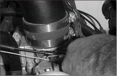
21. Tighten the hose clamp on the silicone hose at the intake tube.
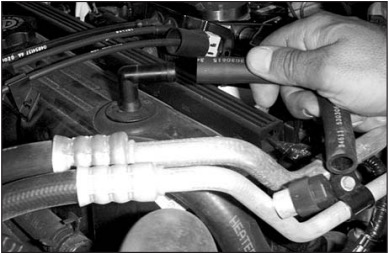
22. Detach the crankcase vent hose from the vent fitting on the valve cover.
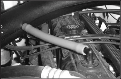
23. Attach the vent hose provided onto the vent fitting on the valve cover and the K&N intake tube.
23a. Reconnect the temperature sensor electrical connection.
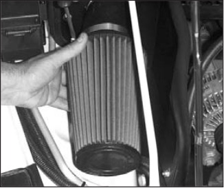
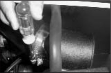
24. Install the K&N Filtercharger element onto the intake tube and tighten the hose clamp provided.
25. Reconnect the vehicle’s negative battery cable. Double check to make sure everything is tight and properly positioned before starting the vehicle.
26. The C.A.R.B. exemption sticker, (attached), must be visible under the hood, so that an emissions inspector can see it when the vehicle is required to be tested for emissions. California requires testing every two years, other states may vary.
27. It will be necessary for all FIPK’s to be checked periodically for realignment, clearance and tightening of all connections. Failure to follow the above instructions or proper maintenance may void warranty.
ROAD TESTING:
1. Start the engine with the transmission in neutral or park, and the parking brake engaged. Listen for air leaks or odd noises. For air leaks secure hoses and connections. For odd noises, find cause and repair before proceeding. This kit will function identically to the factory system except for being louder and much more responsive.
2. Test drive the vehicle. Listen for odd noises or rattles and fix as necessary.
3. If road test is fine, you can now enjoy the added power and performance from your kit.
4. K&N suggests checking the Filtercharger element periodically for excessive dirt buildup. When the element becomes covered in dirt (or once a year), service it according to the instructions on the Recharger service kit, part number 99-5050 or 99-5000.
