 FREE 1 to 3-Day Delivery on Orders $149+ Details

How to Install a JKS Front Swaybar System on your 1997-2006 Jeep Wrangler TJ
Installation Time
3 hours
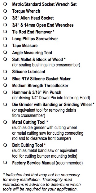
Tools Required
- Metric/Standard Socket Wrench Set
- Torque Wrench
- 3/8" Allen Head Socket
- 3/4" & 14mm Open End Wrenches
- Tie Rod End Remover *
- Long Philips Screwdriver
- Tape Measure
- Angle Measuring Tool
- Soft Mallet & Block of Wood * (for seating bushings into crossmember)
- Silicone Lubricant
- Blue RTV Silicone Gasket Maker
- Medium Strength Threadlocker
- Hammer & 3/16” Pin Punch (for driving 1/4” Dowel Pin into Indexing Head)
- Die Grinder with Sanding or Grinding Wheel * (or equivalent tool for removing debris from crossmember)
- Metal Cutting Tool * (such as die grinder with cutting wheel or metal cutting saw for cutting connecting rod and to clearance front bumper)
- Bolt Cutting Tool * (such as metal band saw or equivalent tool for cutting bumper mounting bolts)
- Factory Service Manual (recommended)
- * Indicates tool that may not be necessary for every installation. Thoroughly read instructions in advance to determine which tools will be required for your application.
Welcome
CONGRATULATIONS on purchasing a SwitchBlade™ Swaybar System from JKS Manufacturing. We are committed to providing you with the best products available and your satisfaction is our first priority.
PLEASE READ these Installation Instructions carefully, and save them for future reference, as they contain important installation and maintenance information.
WE WELCOME your feedback regarding these Installation Instructions and appreciate any suggestions you may have to improve this document for other users.
Important
TUBULAR FRONT CROSSMEMBER must be intact and free of damage in order to install this product. Page 2
CHECK BUMPER COMPATIBILITY before installing. It may be necessary to modify or replace front bumper to ensure proper clearance for this product. Pages 2 & 6
STEERING STOP ADJUSTMENTS may be necessary to prevent interference between tires and blade arms at full steering lock. Page 6
Tools Required
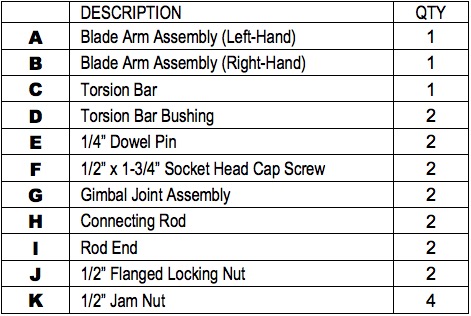
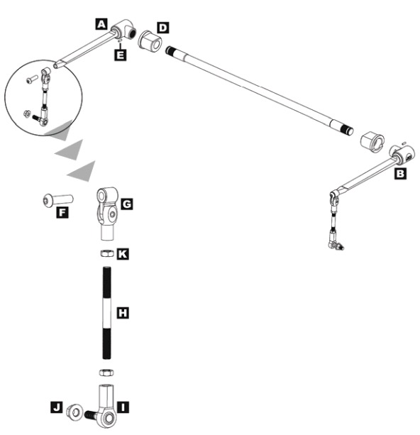
Parts
Attention Installer
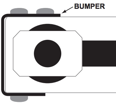
BEFORE YOU INSTALL THIS PRODUCT, verify the front bumper and its mounting system do not interfere with the D-shaped tubular crossmember openings or surrounding area, as illustrated below.
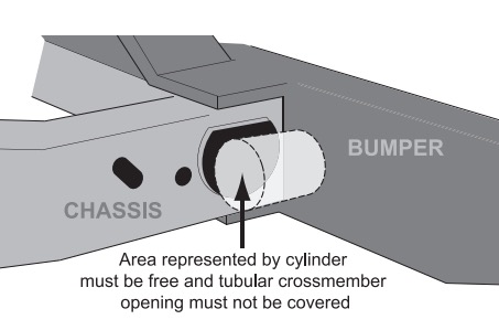
If the bumper interferes with this product, it will be necessary to clearance the bumper or mounting system to allow fitment. Due to the number of possible bumper configurations and other variables beyond our control, we cannot provide instructions for this procedure nor can we encourage it to be attempted.
If any bumper modifications are necessary to install this product, it is the sole responsibility of the installer or vehicle owner to ensure the work is performed properly and neither structural integrity nor safety have been compromised.
Installation
1. REMOVE FRONT BUMPER
Disconnect any auxiliary driving/fog lamps mounted to front bumper, if equipped.
Remove the mounting hardware that secures the front bumper to the chassis.
Remove the front bumper assembly from the vehicle.
Remove the front bumper valence from the chassis.
2. REMOVE FRONT SWAYBAR
Remove the mounting hardware that secures the front swaybar links to the swaybar and axle housing. HINT: If difficult to remove, use special factory removal tool PN MB991113 (Miller Special Tools, 800-801-5420) or similar tie rod end removal tool.
Remove swaybar links from vehicle.
Remove swaybar mounting bolts and bushing retainers from chassis.
Remove front swaybar from vehicle.
3. PREPARE FRONT CROSS MEMBER
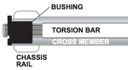
The SwitchBlade Swaybar mounts through the tubular crossmember that connects the chassis rails together immediately forward of the steering box. Crossmember must be intact and free of damage in order to install this product.
Inspect the inside surface at each end of the crossmember for any debris or deformation that could interfere with installation of Torsion Bar Bushings (D).
Clean any mud, dirt, rust, burs, slag, or other debris from inside ends of crossmember.
HINT: A die grinder with sanding wheel or similar tool is useful for removing stubborn debris.
4. INSTALL TORSION BAR
Insert a Torsion Bar Bushing (D) into each end of the tubular crossmember. HINT: A block of wood and soft mallet may be useful to fully seat bushing into crossmember. Do not use brute force – only light tapping with mallet. A light application of silicone lubricant to outer surface of bushing may also be used. If bushings are still difficult to insert, contact JKS at (308) 762-6949 for technical assistance.
Wipe down the Torsion Bar (C) with a light application of Silicone lubricant.
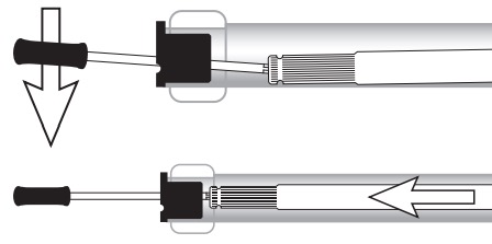
Install Torsion Bar (C) by guiding it through the Torsion Bar Bushings (D) until it is centered.
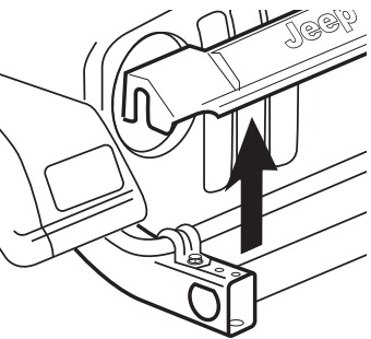
HINT: To guide torsion bar through bushing at far end of crossmember, insert a Philips head screwdriver through bushing and into center hole of torsion bar as illustrated below. Pry torsion bar up using screwdriver while pushing it through the bushing from the opposite end.
Use caution to avoid damaging bushings when installing torsion bar.
5. INSTALL BLADE ARMS
Locate the Blade Arm Assemblies (A & B) and identify their correct mounting location by reading the label applied to the Indexing Heads. “RH” indicates Right-Hand side, and “LH” indicates Left-Hand side. Hint: When installed correctly, the 1/4” through-hole will be on bottom of Indexing Head.
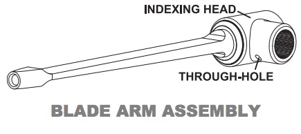
Slide the splined opening of the Indexing Head on to end of Torsion Bar (C). HINT: It may be necessary to gently tap side of Indexing Head with a rubber mallet to fully engage splines. Use a clean, soft towel to protect the polished finish.
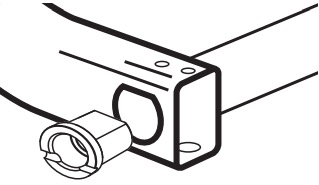
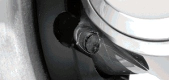
Slowly pivot the Blade Arm Assembly (A) up or down until the 1/4” through-hole in Indexing Head aligns with the access groove in the Torsion Bar Bushing (D) as illustrated below.
Insert a 1/4" Dowel Pin (E) into the through-hole as shown below.
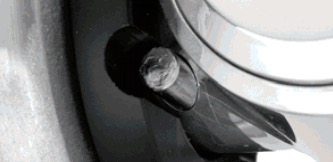
Drive the 1/4” Dowel Pin (E) into through-hole until it is centered as shown below. HINT: A hammer and 3/16” punch are useful for driving the locking pin into position.
With pin installed, fill the rest of the throughhole with blue RTV silicone. Do this on front and back of indexing head. This step is important – do not skip. Silicone will seal through-hole from both ends to prevent any moisture or debris from entering.
Repeat this process to install the second Blade Arm Assembly (B), making sure both arms are perfectly aligned before installing pin. HINT: If arms are not aligned, remove the second arm and rotate up or down by one spline until arms are mounted on the exact same plane.
Blade Arms must be perfectly aligned with each other before proceeding.
6. PREPARE END LINKS
To ensure proper swaybar operation, the supplied End Links must be adjusted to the appropriate length for your application. Adhere to the following instructions carefully to determine the correct process for your vehicle.
With the vehicle at normal ride height and located on level ground, pivot the Blade Arms (A & B) until they are level or parallel (within 2.5 degrees) with the ground as illustrated below.
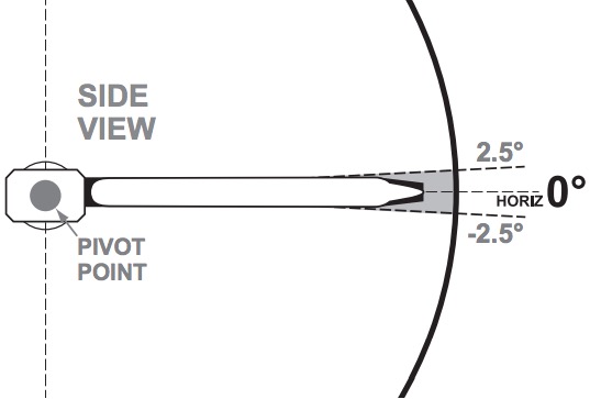
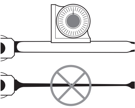
HINT: An angle measuring tool placed directly on the Blade Arm is useful for verifying angle. Always measure blade arm in vertical position to ensure taper in horizontal position does not affect results.
Rotate the Blade Arms (A & B) to the proper angle and hold them in position. HINT: A board, length of pipe, or similar object clamped to one Blade Arm is useful for holding in position.
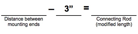
While holding the Blade Arms (A & B) at the proper angle, measure the distance between the center of the hole at the end of each Blade Arm and the original swaybar link mounting holes on the axle bracket.
Subtract 3" from the distance recorded above to determine the modified length of the Connecting Rod (H). HINT: For instance, if the center-tocenter distance for your application is 10", the modified Connecting Rod length should be 7"
7. MODIFY CONNECTING ROD
The supplied Connecting Rods (H) are long enough to accommodate an infinite range of lift heights. On most applications, they must be shortened to set the swaybar at the proper angle. This is accomplished by removing excess material from the Connecting Rods, based on the modified length measurement (from previous step) and the instructions that follow.
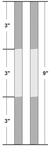
Now that you know the modified Connecting Rod (H) length for your application, you will need to cut them to size.
If your modified length is 4.5” or greater, proceed to step 7a. If your modified length is less than 4.5”, skip ahead to step 7b.
Step 7a
A modified Connecting Rod length of 4.5” or greater is achieved by removing an equal portion of threaded material from each end.
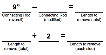
Subtract the modified Connecting Rod length from the overall length of 9” and then divide by 2 to determine the amount of excess material to remove from each end. HINT: For instance, if the modified Connecting Rod length for your application is 7”, the amount of material to remove from each end will be 1”.
Example: 9 - 7 = 2 and 2 ÷ 2 = 1
Skip to Step 7c.
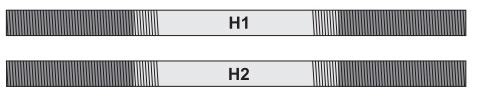
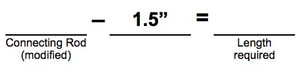
Step 7b
A modified Connecting Rod length shorter than 4.5” is achieved by using a portion of the threaded material at each end of a single rod and discarding the rest.
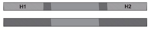
Subtract 1.5” from the modified Connecting Rod length to determine the amount of threaded rod required for your application. HINT: For instance, if the modified Connecting Rod length for your application is 4”, the amount of threaded rod needed is 2.5”.
Example: 4 - 1.5 = 2.5”
Proceed to Step 7c.
Step 7c
The Connecting Rods (H) are loosely installed on the Blade Arms (A & B) by the manufacturer and must be removed before they are modified.
Unthread the Connecting Rod (H) with Rod End (I) and 1/2” Jam Nuts (K) from the Gimbal Joint Assembly (G).
Remove Rod End (I) from Connecting Rod (H), but do not remove 1/2” Jam Nuts.
HINT: Jam Nuts will help stabilize and elevate the Connecting Rod for easier cutting. They can also be used after cutting to chase the threads and repair any damage.
Using the information from Step 7a or 7b, mark the Connecting Rod (H) to indicate the appropriate locations to cut.
HINT: Cut same amount of thread material from each end.
Using an appropriate cutting tool (such as a die grinder with cutting wheel, or metal cutting saw), carefully and squarely cut each end of the Connecting Rod (H) where previously marked.
Now completely unthread both 1/2” Jam Nuts (K) from Connecting Rod (H) and re-install.
HINT: This will help repair any thread damage that may have occurred during the cutting process.
8. INSTALL END LINKS
Apply a drop of medium strength thread locking compound to the tip of threads at each end of Connecting Rod (H).
Completely thread Gimbal Joint Assembly (G) and Rod End (I) back on to Connecting Rod, making sure both ends have a corresponding 1/2” Jam Nut (K).
Using the supplied 1/2” Flanged Locking Nuts (J), secure the lower end of Adjustable End Links to the axle bracket. Make sure Rod Ends (I) are in alignment with mounting brackets. Rod End must be installed on inboard side of axle bracket.
Once all adjustments are complete, fully tighten the Jam Nuts (K) against the Gimbal Joint Assembly (G) and Rod End (I) to prevent length of Adjustable End Links from changing.
Using a torque wrench with a 15mm socket, tighten the 1/2” Flanged Locking Nuts (J) to 40 ft-lbs.
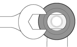
HINT: Use a 14mm wrench on flat spot of Rod Ends (I) to prevent mounting stud from spinning when tightening 1/2” Flanged Locking Nut (J).
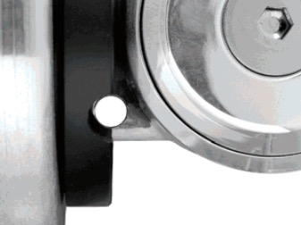
9. MODIFY FRONT BUMPER MOUNTING BOLTS
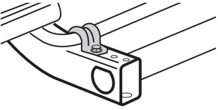
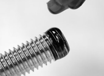
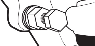
If your bumper mounts to the chassis using the factory mounting holes pictured below (arrow), you must shorten or replace the mounting bolts as described in this section to avoid damaging the torsion bar bushings (not pictured).
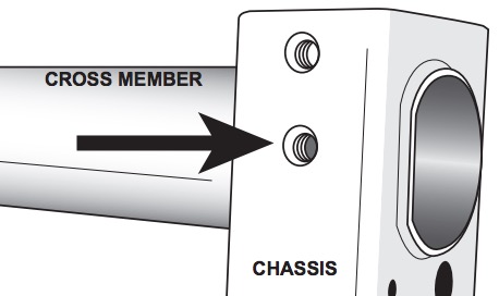
HINT: If bumper mounting bolt is too long it can protrude into the crossmember and damage the torsion bar bushing.
To determine the maximum bolt length for your application, measure the thickness of your bumper (and any washers or other required hardware) where it mounts to the chassis.
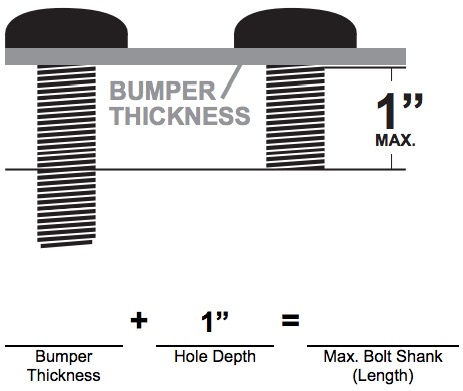
You must account for thickness of bumper and any related hardware when determining maximum bolt length.
Replace the two original bumper mounting bolts with shorter bolts of the same exact size. Make sure new bolt shank is no longer than the Maximum Bolt Length value above.
– OR –
Shorten the two original bumper mounting bolts so that the shanks are no longer than the Maximum Bolt Length value above.
HINT: Carefully cut bolts using a metal cutting tool capable of a clean, square cut to ensure reinstallation. It may be necessary to repair any damaged threads with a small file.
10. VERIFY BUMPER CLEARANCE
With the SwitchBlade Swaybar installed, slide your front bumper into its mounting position on the chassis and loosely install hardware.
Rotate the Blade Arms (A & B) up and down while checking for sufficient clearance between the Indexing Head and the front bumper, as illustrated below.
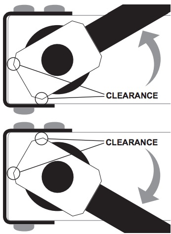
If Indexing Head interferes with bumper, it will be necessary to clearance the bumper until the Indexing Head can rotate without interference.
HINT: A die grinder with metal cutting wheel or similar tool is useful for removing material from the bumper. Remove only as much material as is necessary and use caution to avoid compromising structural integrity.
11. RE-INSTALL FRONT BUMPER
Re-install the front valence on the chassis, if equipped.
Slide your front bumper into its mounting position on the chassis.
Apply a drop of medium strength thread locking compound to the tip of “short” bumper bolts (from step 9).
Re-install the mounting hardware that secures the bumper to the chassis.
Using a torque wrench, tighten bolts that secure bumper to chassis to 80 ft-lbs. (or whatever the original bumper manufacturer recommends).
Reconnect any auxiliary driving/fog lamps mounted to bumper, if equipped.
12. ADJUST STEERING STOPS OPTIONAL
One of the most common issues that Wrangler TJ owners face when running oversized tires is interference between the tires and front swaybar or control arms at full steering lock. Oftentimes the issue is ignored without any serious consequences; the tires may rub through the paint to expose bare metal, but no real damage is done.
But for those who want to address the issue, there is a simple and easy solution.
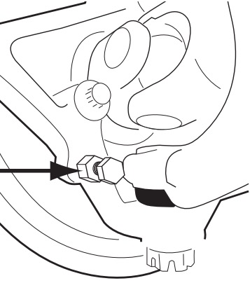
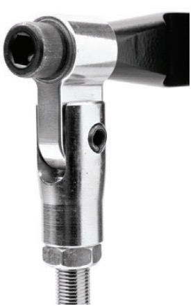
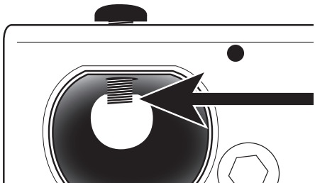
Inspect the front steering knuckles near the lower ball joints and you will notice a small bolt threaded into a welded nut (arrow). This is the factory steering stop adjuster.
The head of this bolt limits steering by contacting the corresponding steering stop on the axle at full steering lock. To adjust the steering limits, you can shim the steering stop adjuster bolt using ordinary flat washers.
Simply remove the adjuster bolt with welded nut from the steering knuckle.
Once removed, place a 7/16” or 3/8” flat washer on the bolt and re-install the part on the steering knuckle. HINT: To reduce tire rubbing when turning left, you’ll need to adjust the steering stop on the right knuckle. And to reduce rubbing when turning right, you’ll adjust the steering stop on the left knuckle.
You may need to install multiple washers if interference still occurs. For most applications, one to three washers per side will suffice. Just remember that your turning radius will decrease slightly with each washer added.
And on some applications, it is not possible to completely eliminate interference. If you encounter any problems with your installation and setup, please contact JKS Manufacturing for technical assistance.

Maintenance
Regular cleaning with pressurized water is recommended to maximize ease of operation and reliability.
