 FREE 1 to 3-Day Delivery on Orders $149+ Details

How to Install G2 Dana 30F/44R - 4.56 Gears on your 07-18 Jeep Wrangler JK Rubicon; 2018 Jeep Wrangler JL Rubicon
Installation Time
6 hours
Tools Required
- Eye protection
- Dial indicator with magnetic stand
- Gear marking compound and brush
- Calipers or micrometer
- Bearing puller
- Bearing press
- Three foot long breaker bar or strong impact gun
- Pinion nut socket
- Ring gear bolt socket
- Carrier cap bolt socket
- Six point cross pin bolt wrench
- Brake line wrench
- Pry bars for removing the carrier case
- 24 oz ball peen hammer
- 48 oz sledge hammer
- 48 oz plastic dead blow hammer
- Brass punch
- Punch for marking carrier caps
- Oil drain pan
- Foot pounds torque wrench
- Inch pounds torque wrench
- Pinion depth setting tool

Shop Parts in this Guide
PLEASE READ THE FOLLOWING:
Ring and pinion sets are not just installed, they are set up using shims and or adjusters to achieve a proper “contact pattern.” The difference between a correct set up and an incorrect set up can be measured in thousandths of an inch. (.001), resulting in either quite, extended gear life, or noisy, premature wear, and failure. Because of this, G/2 Axle & Gear strongly recommends this gear set be professionally installed. Should you prefer to do the installation yourself, please read these instructions carefully. Depending on your experience, you may want to have a factory service manual available during the install.
All ring and pinion sets are manufactured as a matched pair. The ring and pinion should never be mixed with another gear set, as they have been lapped together for optimum strength and quiet operation. The ring gear and the pinion gear will have matching “hand etched” numbers engraved on them for verification.
Disassembly
1. Prior to disassembly always make sure you have everything required to finish the job.
Check all new part to confirm that you have the correct parts that you ordered, and
that they have not been damaged during shipping.
2. Begin by lifting the vehicle with the appropriate lift or jack. Use proper jack stands
to support the vehicle.
3. Drain the oil and dispose of properly. Preferably at a recycling center near you.
4. Remove axle shafts.
5. Mark both bearing caps to ensure proper reassembly.
6. Remove the old gear set and clean the carrier and housing assembly thoroughly
(including the axle tubes).
7. Make note of the position and thickness of the original shims. This will be helpful
during the installation process.
8. Inspect all parts for excessive wear or damage and replace if necessary. You may
want to pay particular attention to your wheel bearings and axle shafts at this point,
especially on c-clip type axles as they are prone to wear.
9. Clean all parts that will be reused in the assembly process with clean solvent. You
may want to pay close attention to the oil passages to the pinion bearings and the axle
tubes as metal particles and dirt can collect in these areas.
Pre-Assembly
1. Clean the new ring and pinion gear set to remove any protective coating and /or
packing material.
2. After cleaning, dry all parts with an air supply, making sure to not spin the bearings
with compressed air (USE EYE PROTECTION).
3. Inspect the tooth areas of both gears for any small chips that may have occurred
during shipping. Dress with a small fine file as needed.
4. Examine the mounting surface of the ring gear and the mating surface of the carrier
for any nicks, burrs or irregularities that might prevent a flush mounting of the ring
gear. Ring and pinion tooth depth and backlash variations can result from a ring gear
that is “cocked” on the carrier mounting surface.
5. Mount the ring gear to the carrier carefully, making sure there are no burrs created
between the two surfaces. Check ring gear bolts for proper length, Use a very small
amount of thread locking compound on the ring gear bolt threads and torque to specs.
6. Clean all seal surfaces with a fine emery cloth, and wipe clean.
Assembly
During the ring & pinion installation, there are four primary adjustments that will need to be made.
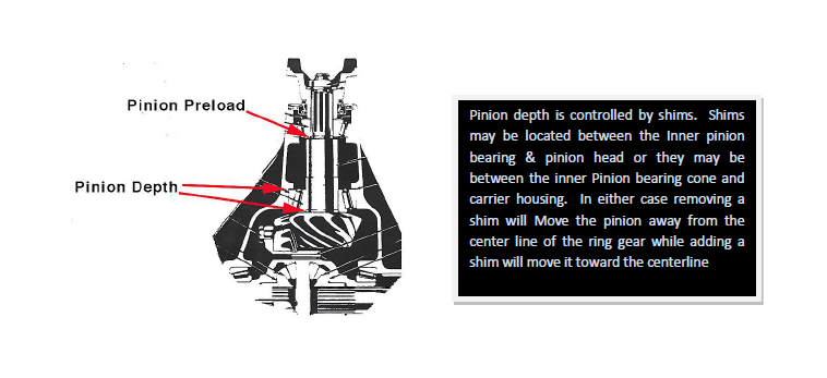
1. Pinion Depth – The distance from the face of the pinion gear to the centerline of the
ring gear. This is adjusted by adding or subtracting shims to the inner pinion bearing.
2. Pinion Bearing Preload-The preload applied to the pinion bearings when the pinion
nut is tightened. This is adjusted by shims and/or a crush sleeve.
3. Backlash – The distance between the mating surfaces of the ring and pinion gears.
Adjusted by moving the ring gear inward or outward from the pinion gear by
shimming the carrier.
4. Carrier bearing preload – The preload applied to the carrier bearings when installed in
the axle housing.
1. Setup Without Pinion Depth Setting Tool
In order to obtain the correct set up without a pinion depth setting tool, the following
procedure is suggested:
a. Unless otherwise instructed, start with the original pinion depth shim. On most
rear ends this will require a bearing puller such as (G2 80-BRGPLLR) to remove
the old pinion bearing from the original pinion.
b. Press the new bearing on the new pinion shaft using the original shim.
c. After replacing the pinion races, install the new pinion into the housing without a
crush collar/preload shims and without the pinion seal.
d. Use the old pinion nut to secure the yoke and tighten to obtain the factory
specified preload.
e. Tap on the yoke a few times to ensure that the races are fully seated and recheck
your pinion preload tighten the nut to reset the preload to factory specs.
f. Install the carrier to fit snugly in the housing and set the backlash to
approximately .008” to .010” by changing the carrier shims (or adjusters) on each
side as required.
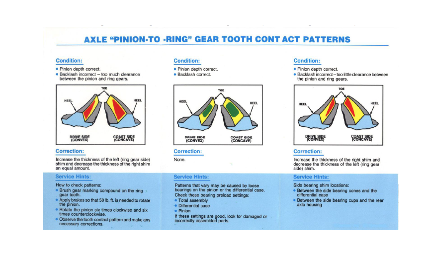
g. You can now check the tooth pattern by using marking compound on the ring gear
teeth. Add or subtract pinion depth shims in increments of .003” to obtain a new
pattern.
h. Adjust carrier shims to obtain the proper backlash specified for your application
when making pinion depth changes.
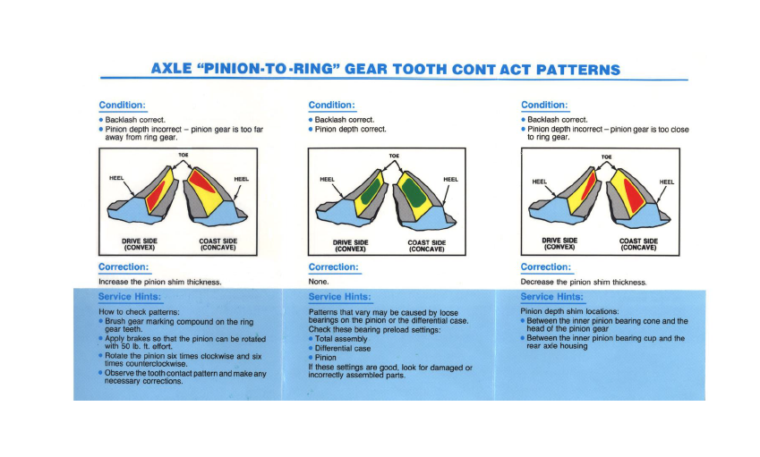
i. Refer to the desired pattern as indicated in the Tooth Contact Pattern chart.
j. After the proper pattern has been established, you can remove the carrier, remove
the pinion, and install the crush sleeve and or preload shim stack along with a new
pinion seal and nut. (use thread locker on the nut)Set pinion preload to factory
specs.
k. Reinstall the carrier assembly and recheck the backlash, pattern, and carrier
preload. Torque main caps to factory specs.
2. Setup With Pinion Depth Setting Tool
a. Start by installing the pinion in the housing as per the pinion depth dimensions.
This depth is obtained by using pinion shims behind the inner pinion bearing or
behind the inner pinion race or between the pinion support and the case (Ford 9”
and GM 10.5”)
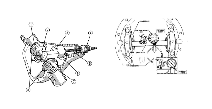
b. See figure 1. The thickness of the pinion shims is determined by using a pinion
depth setting tool measure the checking distance. Obtaining the correct pinion
depth is very critical.
c. After obtaining the correct pinion depth setting, install a new crush collar, outer
pinion bearing, pinion seal, yoke and new pinion nut. (NOTE: do not reuse a
crush collar or pinion nut).
d. Torque the pinion nut to the crush collar and establish the correct pinion preload.
It requires approximately 180ft./lb of torque to begin to crush the collar. Once the
nut has become tight and all endplay has been removed, slowly continue to
tighten the nut and crush the collar until the proper preload has been established.
(CAUTION: The preload is measured in INCH PUONDS) Do not over tighten
the crush collar. If this occurs a new collar MUST be installed and the procedure
repeated.
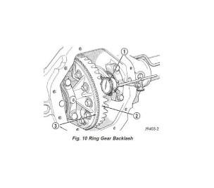
3. Adjusting Backlash
a. After the pinion is properly installed, install the carrier assembly in the housing. Be sure the carrier bearings and races are fully seated and that the entire assembly, with shims, fits snugly in the housing.
b. Mount a dial indicator on the housing in a matter that will allow the plunger to travel in the same plane as the ring gear. While holding the pinion stationary, move the ring gear back and forth and observe the dial indicator. The total movement is the backlash. Measure and record the backlash in three places equally spaced around the ring gear. This will provide you with an accurate backlash reading.
c. Adjust backlash to specs using the carrier shims or adjusters. A total backlash variance of .003” is acceptable.
4. As a final step you must check the tooth contact pattern with marking compound to assure that the specifications produced the correct patterns. (Refer to the pattern chart)
Break In Procedure
All gear sets require a brief break in procedure to ensure long life and quiet operation. The following is recommended before any heavy load and or constant use: Insure the housing is filled to the correct level using the proper lubricant (including additives if required).
1. Bring axle to operating temperature by driving (unloaded) for approximately 15 to 20
minutes. Do not create any heavy shock loads.
2. Let the axle assembly cool completely.
3. For the next 200 miles of operation, drive normally, without any heavy loads.
4. If trailer towing is intended, an additional 200-300 mile break in without trailer is
required. This is important! To properly break in a new set of gears, a minimum of 500
miles of driving is essential before constant towing.
5. Change the gear oil after the first 500 miles to remove any metal particles that come from breaking in a new gear set.
IF THIS PROCEDURE IS NOT FOLLOWED, OVERHEATING AND EVENTUAL
GEAR AND/OR BEARING FAILURE MAY RESULT.

