 FREE 1 to 3-Day Delivery on Orders $149+ Details

How to Install a Fabtech 3 in. Basic Lift Kit W/ Dirt Logic Shocks on your 2007-2015 Jeep Wrangler J
Installation Time
1 days
Tools Required
- Basic Hand Tools
- Floor Jack
- Jack Stands
- Assorted Metric and S.A.E sockets, and Allen wrenches
- Torque Wrench
- Pitman Arm Puller
- Ball Joint Split Fork
- Welder
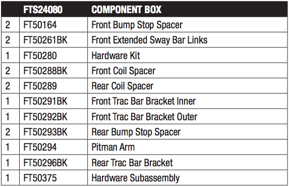
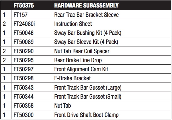
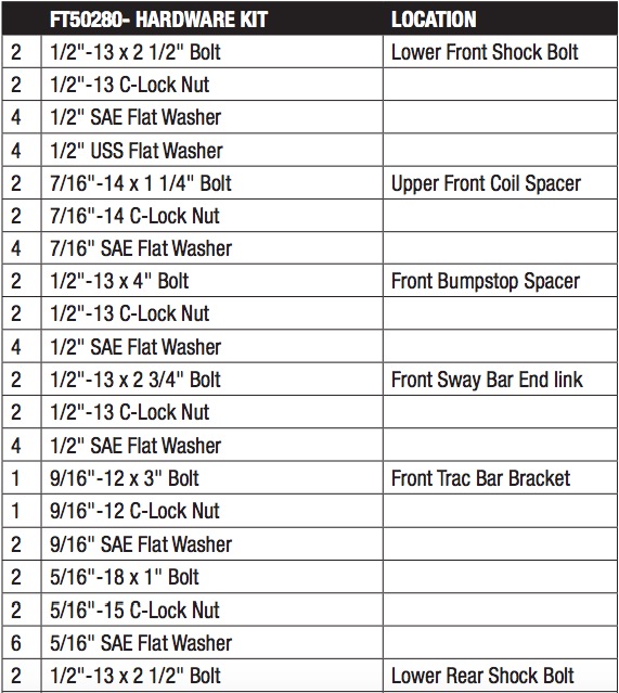
Parts List

PRE-INSTALLATION NOTES
For technical assistance call: 909-597-7800 or e-mail: [email protected]
Read this before you begin installation -
Check all parts to the parts list above before beginning installation. If any parts are missing contact Fabtech at 909-597-7800 and a replacement part will be sent to you immediately.
Read all instructions thoroughly from start to finish before beginning the installation. If these instructions are not properly followed severe frame, driveline and / or suspension damage may occur.
Check your local city and state laws prior to the installation of this system for legality. Do not install if not legal in your area.
Prior to the installation of this suspension system perform a front end alignment and record. Do not install this system if the vehicle alignment is not within factory specifications. Check for frame and suspension damage prior to installation.
The installation of this suspension system should be performed by two professional mechanics.
This suspension must be installed with Fabtech shock absorbers.
Use the provided thread locking compound on all hardware.
WARNING- Installation of this system will alter the center of gravity of the vehicle and may increase roll over as compared to stock.
Vehicles that receive oversized tires should check ball joints, uniballs, tie rods ends, pitman arm and idler arm every 2500- 5000 miles for wear and replace as needed.
Verify differential fluid is at manufactures recommended level prior to kit installation. Installation of the kit will reposition the differential and the fill plug hole may be in a different position. (For example, if the manufacture recommends 3 quarts of fluid, make sure the diff has 3 quarts of fluid). Check your specific manual for correct amount of fluid.
Welding is required for the installation of this suspension system
NOTE: When lifting 2012 and newer models the driveshaft will make contact with the factory exhaust system. We prefer the use of AFE’s Part #49-46230 (Y-Pipe).
REQUIRED DRIVESHAFTS -
| 1 | FTS94057 | 2007-14 Front Driveshaft 2 & 4 Door Models |
| 1 | FTS94051 | 2007-11 Rear Driveshaft 2 Door Model Only |
| 1 | FTS94052 | 2007-11 Rear Driveshaft 4 Door Model Only |
| 1 | FTS94058 | 2012-14 Rear Driveshaft 2 Door Model Only |
| 1 | FTS94059 | 2012-14 Rear Driveshaft 4 Door Model Only |
INSTRUCTIONS
FRONT SUSPENSION
1. Disconnect the negative terminal on the battery. Jack up the front end of the truck and support the frame rails with jack stands. NEVER WORK UNDER AN UNSUPPORTED VEHICLE! Remove the front tires.
2. Working from the driver side of the truck, unbolt the front brake line bracket from the frame and save the hardware. Remove the ABS sensor wire from the C-Clips on the front knuckle. Remove and discard the sway bar endlinks, save the hardware. Unplug the front diff locker harness from the axle (RUBICON MODELS ONLY)
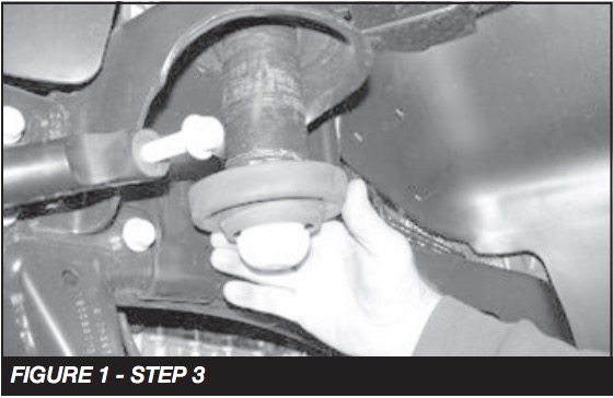
3. Remove the front shock, save lower mount hardware, and discard upper. Remove the factory coil spring, and save, you will need to allow the front axle to hang freely to remove the coil spring. Remove the factory upper coil isolator, and save. SEE FIGURE 1
4. Repeat steps two and three on the passenger side of the Jeep.
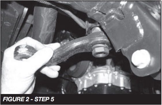
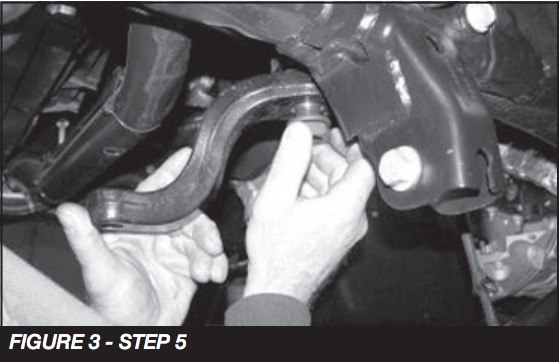
5. Remove and save the trac bar and hardware. Use a split fork and separate the draglink from the pitman arm, save hardware. Use a pitman arm puller and remove the stock pitman arm. Discard the arm and save the nut and washer. Locate the FT50294 pitman arm and install in the same position as the stock one was with the factory hardware. Torque to 185 ft-lbs. SEE FIGURES 2-3
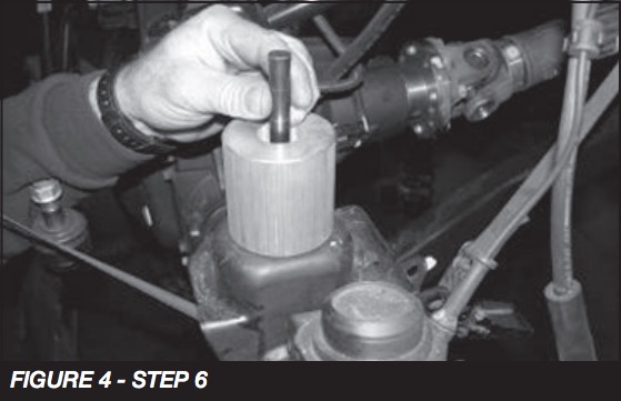
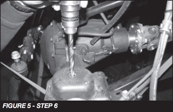
6. Locate FT50164 Front Bumpstop Spacer position it on the center of the coil spring mount and mark with a center punch. Use a drill with a ½” bit and drill the new hole to mount the new Fabtech spacer. (DO NOT INSTALL AT THIS TIME) SEE FIGURES 4-5
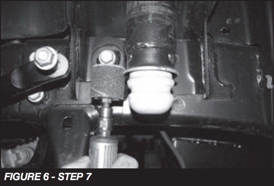
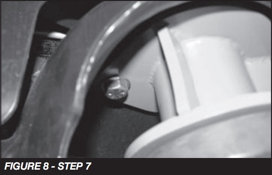
7. Locate FT50288BK Front Coil Spacer, stock coil spring isolator, and supplied 7/16” x 1 ¼” bolt and hardware. Use a die grinder with a sanding drum and sand down the edge of the factory upper bumpstop. (ONLY SAND ENOUGH TO SLIDE THE COILSPACER AROUND THE UPPER MOUNT). Install the isolator onto the spacer and slide the spacer over the bumpstop and up into the coil bucket. Insert the 7/16” bolt through the spacer and up through the top of the coil bucket. Torque to 55 ft-lbs. SEE FIGURES 6-8

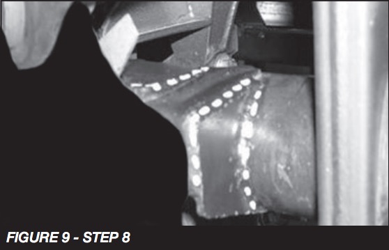
8. Locate FT50344 gusset; position it onto the axle and the factory trac bar mount as shown in photo. Weld the gusset on the three outward / top sides. SEE FIGURE 9
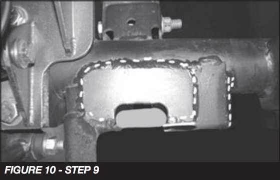
9. Locate FT50343 gusset, position it onto the top of the axle and trac bar mount. Weld the gusset as shown in the photo. SEE FIGURE 10
10. Once the gusset kit has completely cooled, paint all bare metal areas.
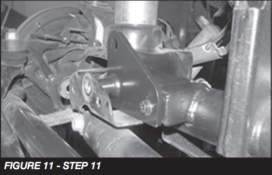
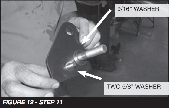
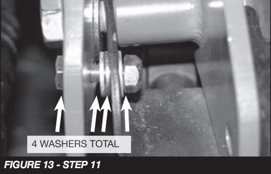
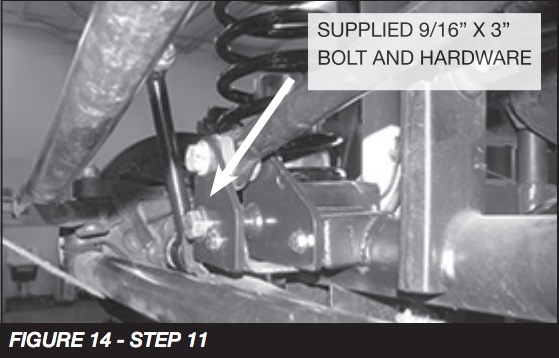
11. Locate FT50291 Front Inner Trac Bar Bracket, FT50292 Front Outer Trac Bar Bracket, supplied 9/16” x 3” bolt , FT50358 nut tab and the supplied 5/16 x 1” hardware. Position the inner bracket into the trac bar mount. Place the 9/16” bolt into the outer bracket and a fl at washer on the back side of the bracket. Attach the outer bracket to the factory trac bar mount with the FT50358 nut tab and leave loose. Take a 5/16” x 1” bolt with a fl at washer and insert it into the outer bracket only. Place two (2) additional fl at washers onto the bolt between the outer bracket and the factory trac bar bracket followed by another washer and nut on the inside of the factory mount. Leave loose. Attach the inner trac bar bracket to the factory mount with the 5/16” hardware. Torque the 5/16” hardware to 20 ft-lbs and the 9/16” bolt to 95 ft-lbs. SEE FIGURES 11-14
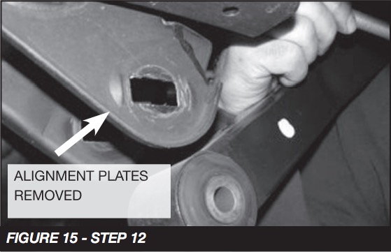
12. Remove the front lower link arm from the differential and discard the factory hardware. Using a small fl at chisel and hammer, remove the alignment plates from the factory mount. Locate the supplied alignment cams and attach the link arms back into the factory mounts. Rotate the cams so that the large part of the lobe is to the front of the axle. Torque to 95 ft-lbs. SEE FIGURES 15-16

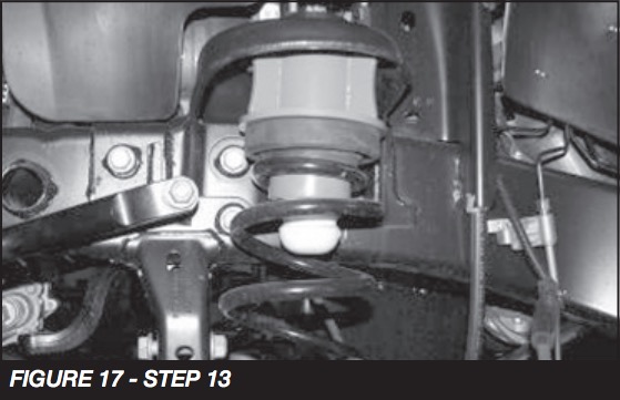
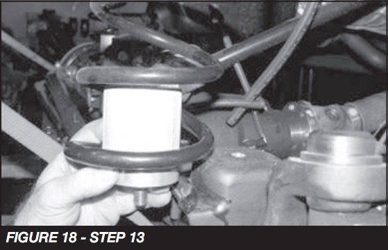
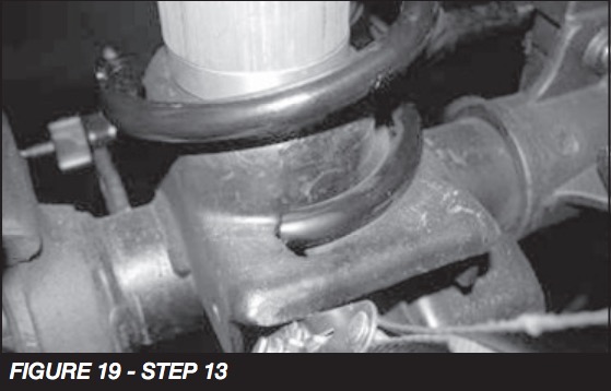
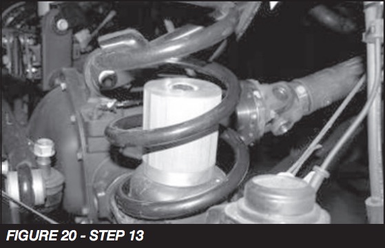
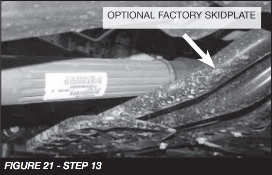
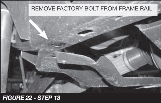
13. Locate the front bumpstop spacer and hardware and place into the bottom of the factory front coils. Reinstall the factory coil spring up onto the new coil spacer and then onto the spring perch on the axle. Rotate the coil spring so that the end of the coil is seated in the perch. Attach the bumpstop spacer onto the previously drilled axle mounts. Note: If your Jeep has the optional skid plate below the front driveshaft, remove the bolts from each side of the frame and ONLY loosen the center bolt. Lowering the skid plate will allow the front differential and driveshaft to be lowered enough to install the driver side coil spring. Re-attach skid plate and torque hardware to 70 ft-lbs once the coil springs are installed. SEE FIGURES 17-22
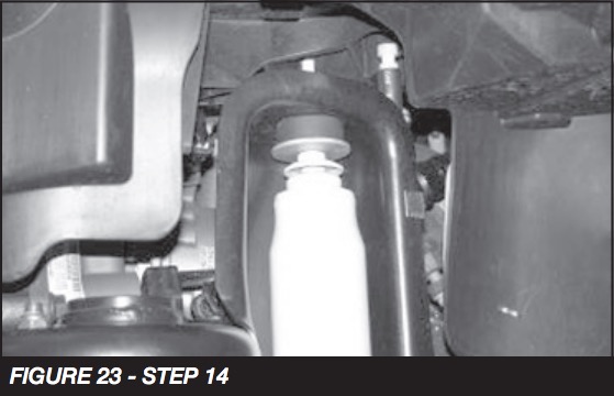
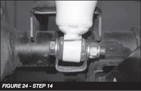
14. Locate the Fabtech shock FTS7236. (Not included in the kit), factory front shocks, the supplied ½” x 2 ½” bolts, USS and Flat Washers, and C-Lock Nuts. Remove the upper bushings and washers from the factory shocks and use to install the new shock to the upper mounting location on the coil bucket. Attach the bottom of the shock to the stock lower shock mount. Use two flat washers on the outside of the mount and two large USS washers on each side of the shock busing on the inside of the mount. SEE FIGURES 23-24
15. Re-install the ABS lines, differential vent tube, and electrical connection for front locker (Rubicon Models Only). Re-attach the brake line bracket to the frame with the factory hardware.
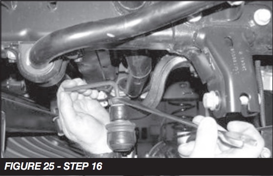
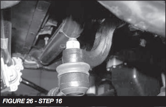
16. Reconnect the inner tie rod end using factory hardware to the new dropped pitman arm. Torque to 45 ft-lbs. SEE FIGURES 25-26
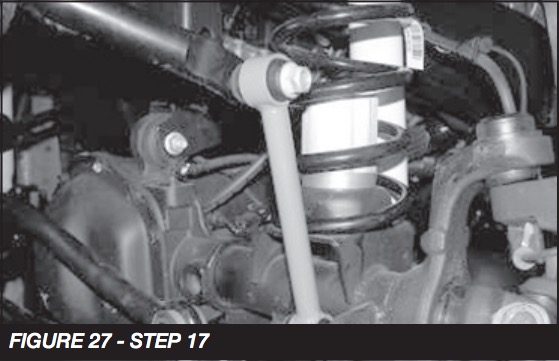
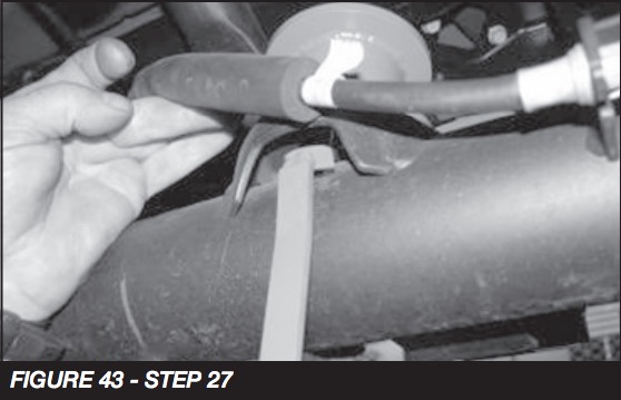
17. Locate FT50261 Front Sway Bar Endlinks, FT50048 & FT5009 bushing and sleeve kits. Press one bushing and one sleeve from the supplied bushing kit into each end of the end link. With the factory hardware, connect the new end link to the sway bar, then using the supplied ½” x 2 3/4” bolt, nut, and washers connect to the lower sway bar mount. Torque the upper hardware to 40 lbs and the lower hardware to 75 ft-lbs. SEE FIGURE 27
18. Install front tires and wheels. Torque lug nuts to wheel manufacturer’s specifications. Turn wheels left to right to check for proper clearance of brake lines, ABS lines, and fenders.
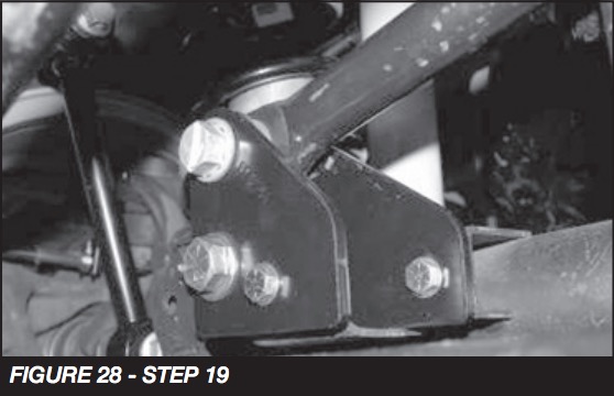
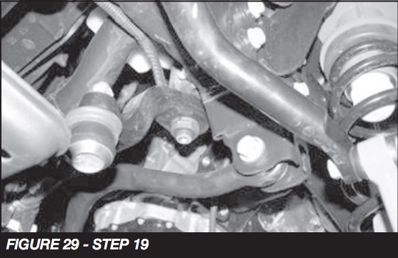
19. Locate the factory trac bar and upper hardware and the lower factory trac bar bolt and nut tab. Position the trac bar into the new mount on the axle and attach with the factory bolt and nut tab. Then attach the trac bar to the factory upper mount with the factory hardware. Torque the factory hardware to 100 ft-lbs. SEE FIGURES 28-29
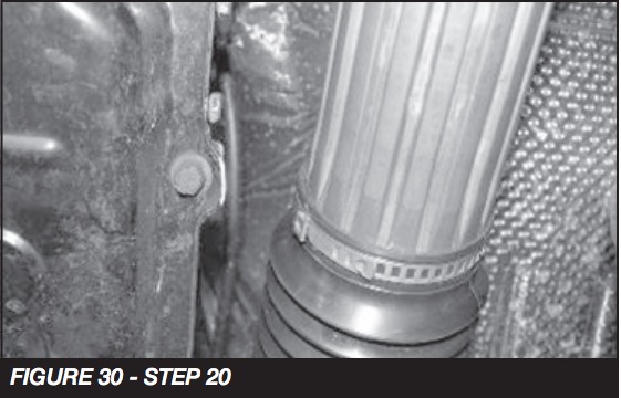
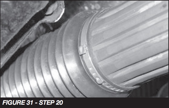
20. Locate the factory front driveshaft boot clamp and remove with out damaging the boot. Locate and install the supplied boot clamp in the factory position. Once the new clamp is installed, use a small hammer and lightly flatten out the crimp section of the clamp. This is done for clearance of the clamp to the transmission during full suspension travel. SEE FIGURES 30-31
REAR SUSPENSION
21. Jack up the rear end of the vehicle and support the frame rails just in front of the rear bumper with jack stands. NEVER WORK UNDER AN UNSUPPORTED VEHICLE! Remove the rear tires. Support the rear axle; do not allow to hang freely.
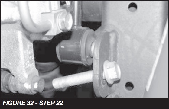
22. Remove the factory shocks and discard, save upper mount hardware. Disconnect the rear sway bar end links at the lower mount on the axle, save hardware. SEE FIGURE 32
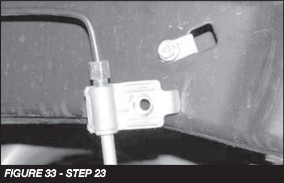
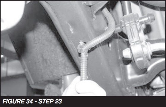
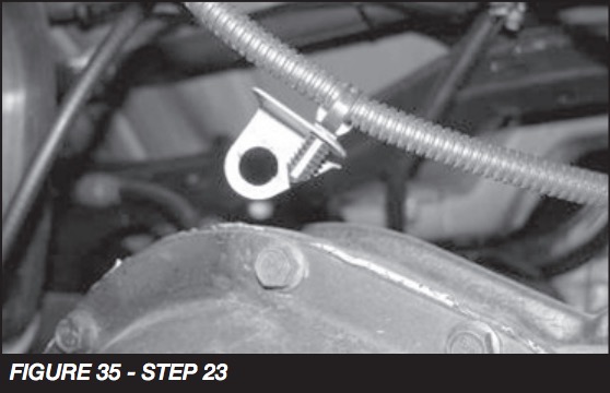
23. Remove the brake line bracket from the frame and save the hardware. Remove the plastic clip that holds the ABS lines to the frame and at the rear upper link arm pockets. Do not damage the clips, they will be reused. Remove the top differential cover bolt and remove the ABS line clamp. Save the bolt. Remove the two nuts holding the E-Brake cable to the body of the Jeep and save. SEE FIGURES 33-35
24. Remove the factory coil springs, and save, you will need to allow the axle to hang freely to remove the coil spring. Remove the factory upper coil isolator and save.
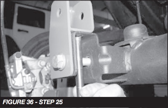
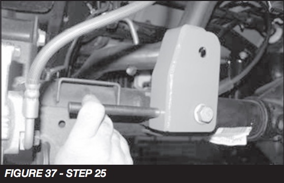
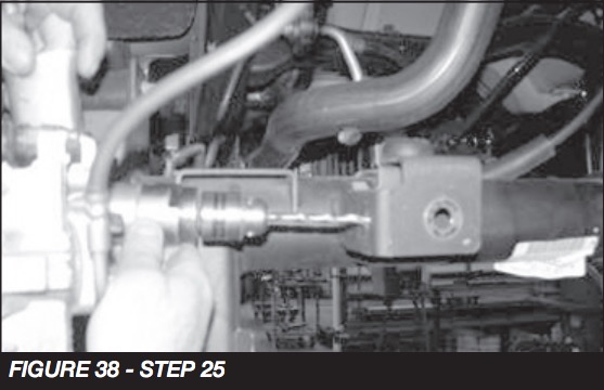
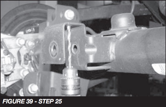
25. Remove the lower trac bar from the trac bar mount on the axle and save the hardware. Locate FT50296 Rear Trac Bar Bracket and position it onto the factory trac bar mount and insert the factory hardware to hold the new bracket in place. Use a center punch and mark the two new 3/8” holes from the bracket onto the mount. Remove the bracket from the mount and use a drill with a 3/8” bit to drill the two new holes. SEE FIGURES 36-39
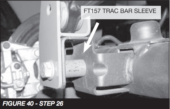
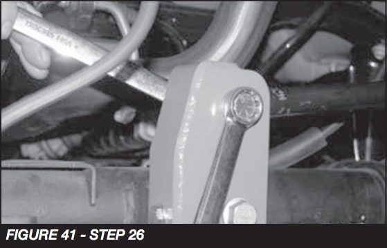
26. Position the trac bar into the new trac bar bracket. Attach the new bracket to the factory mount with the factory hardware and the provided FT157 Sleeve in the factory trac bar mount. Using the provided 3/8” hardware, attach the new bracket to the factory mount and torque to 30 lbs. Torque the factory trac bar bolt to 100 lbs. Attach trac bar to the new mount using the provided 9/16” x 3” hardware. Torque the 9/16” bolt to 95 ft-lbs. SEE FIGURES 40-41
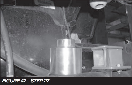
27. Locate FT50289 Rear Coil Spring Spacer and FT50290 Nut Tab. Position the coil spacer onto the factory spring mount using the nut tab and the supplied ½” x 2 ½” bolts with washers and thread-locking compound. Torque to 75 ft-lbs. SEE FIGURES 42-43
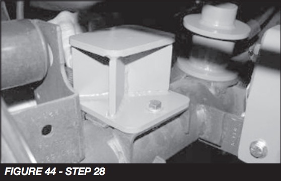
28. Locate FT50293 Rear Bumpstop Spacer. Position the spacer onto the factory bumpstop pad on the axle and attach with the supplied 5/16” x 1” bolts and hardware (mount the spacer to the axle with the offset of the spacer to the front of the Jeep) SEE FIGURE 44
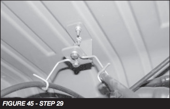
29. Locate FT50298 E-Brake Bracket and supplied ¼” hardware. Position the bracket to the factory mounting position and attach with the factory hardware. Attach the factory bracket to the new Fabtech bracket with the ¼” hardware. Torque to 10 ft-lbs. SEE FIGURE 45
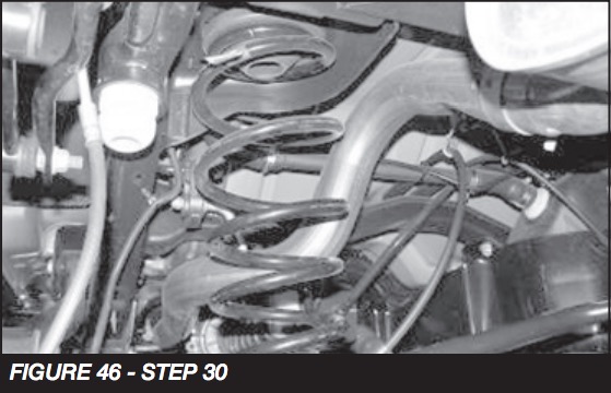
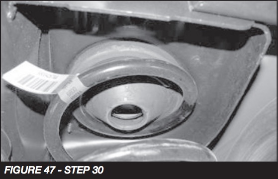
30. Reinstall the factory coil spring with the factory isolators on the top into the upper mount first. Then onto the new coil spacer on the axle. (make sure upper isolator is fully seated into the upper pocket / mount). SEE FIGURES 46-47
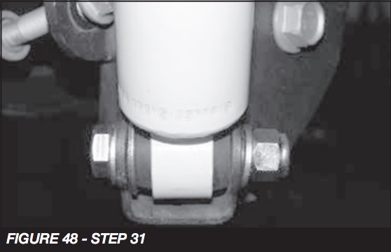
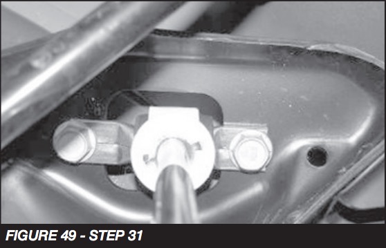
31. Install the Fabtech shock FTS6001 (Not included in the kit) Use the factory upper hardware to mount the bar bin and the supplied ½” x 2 ½” bolt, large USS washers, and hardware. (insert one large USS washer per side inside the shock mount with the shock) Torque the upper hardware to 60 ft-lbs. and the lower to 75 ft-lbs. SEE FIGURES 48-49
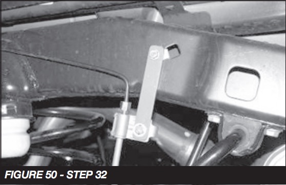
32. Locate FT50295 Rear Brake Line Drop Bracket, supplied ¼” hardware, and factory rear brake line hardware. Attach the drop bracket to the factory mount with the factory hardware. Attach the factory brake line bracket to the new drop bracket with the ¼” hardware. Torque to 10 ft-lbs. SEE FIGURE 50
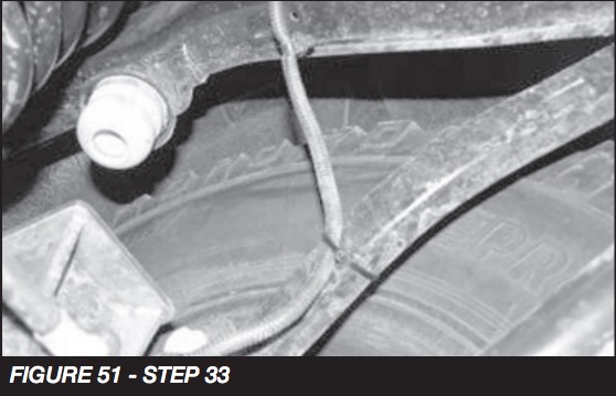
33. Reconnect the factory ABS mount to the rear differential and torque to 20 ft-lbs. Route the ABS line in the stock routing and attach the line to the upper link arm with the supplied 8” zip ties (DO NOT reinsert the plastic clips into the frame). SEE FIGURE 51
34. Install tires and wheels and torque lug nuts to wheel manufacturer’s specifications. Turn front tires left to right and check for appropriate tire clearance. Note - Some oversized tires may require trimming of the front bumper & valance.
35. Check front end alignment and set to factory specifications. Readjust headlights.
36. Recheck all bolts for proper torque.
37. Recheck brake hoses, ABS wires and suspension parts for proper tire clearance while turning tires fully left to right.
38. Check the fluid in the front and rear differential and fill if needed with factory specification differential oil. Note - some differentials may expel fluid after filling and driving. This can be normal in resetting the fluid level with the new position of the differential/s.
39. Install Driver Warning Decal. Complete product registration card and mail to Fabtech in order to receive future safety and technical bulletins on this suspension.
Vehicles that will receive oversized tires should check ball joints, uniballs and all steering components every 2500-5000 miles for wear and replace as required.
RETORQUE ALL NUTS, BOLTS AND LUGS AFTER 50 MILES AND PERIODICALLY THEREAFTER.
For technical assistance call: 909-597-7800
Product Warranty and Warnings
Fabtech provides a Limited Lifetime Warranty to the original retail purchaser who owns the vehicle, on which the product was originally installed, for defects in workmanship and materials.
The Limited Lifetime Warranty excludes the following Fabtech items; bushings, bump stops, ball joints, tie rod ends, limiting straps, cross shafts, heim joints and driveshafts. These parts are subject to wear and are not considered defective when worn. They are warranted for 60 days from the date of purchase for defects in workmanship.
Dirt Logic and Performance Coilover take apart shocks are considered a serviceable shock with a one year warranty on leakage only. Service seal kits are available separately for future maintenance. All other shocks are covered under our Limited Lifetime Warranty.
Fabtech does not warrant any product for finish, alterations, modifications and/or installation contrary to Fabtech’s instructions. Alterations to the finish of the parts including but not limited to painting, powder coating, plating and/or welding will void all warranties. Some finish damage may occur to parts during shipping, which is considered normal and is not covered under warranty.
Fabtech products are not designed nor intended to be installed on vehicles used in race applications or for racing purposes or for similar activities. (A “RACE” is defined as any contest between two or more vehicles, or any contest of one or more vehicle against the clock, whether or not such contest is for a prize). This warranty does not include coverage for police or taxi vehicles, race vehicles, or vehicles used for government or commercial purposes. Also excluded from this warranty are sales outside of the United States of America.
Installation of most suspension products will raise the center of gravity of the vehicle and will cause the vehicle to handle differently than stock. It may increase the vehicle’s susceptibility to a rollover, on road and off road, at all speeds. Extreme care should be taken to operate the vehicle safely at all times to prevent rollover or loss of control resulting in serious injury or death. Fabtech front end Desert Guards may impair the deployment or operation of vehicles equipped with supplemental restraining systems/air bag systems and should not be installed if the vehicle is equipped as so.
Fabtech makes every effort to ensure suspension product compatibility with all vehicles listed on the website, but due to unknown auto manufacturer’s production changes and/or inconstancies by the auto manufacturer, Fabtech cannot be responsible for 100% compatibility, including the fitment of tire and wheel sizes listed. The Tire and Wheel sizes listed in Fabtech’s website are only a guideline for street driving with noted fender trimming. Fabtech is not responsible for damages to the vehicle’s body or tires. Fabtech is not responsible for premature wear of factory components due to the installation of oversized tires and wheels.
Fabtech’s obligation under this warranty is limited to the repair or replacement, at Fabtech option, of the defective product only. All costs of removal, installation or re-installation, freight charges, incidental or consequential damages are expressly excluded from this warranty. Fabtech is not responsible for damages and/or warranty of other vehicle parts related or non related to the installed Fabtech product. This warranty is expressly in lieu of all other warranties expressed or implied. This warranty shall not apply to any product that has been subject to accident, negligence, alteration, abuse or misuse as determined by Fabtech.
Fabtech suspension components must be installed as a complete system including shocks as shown on our website. All warranties will become void if Fabtech parts are combined and/or substituted with other aftermarket suspension products. Combination and/or substitution of other aftermarket suspension parts may cause premature wear and/or product failure resulting in an accident causing injury or death. Fabtech does not warrant products not manufactured by Fabtech.
Depending on the condition of the factory suspension components retained after the installation of a Fabtech suspension not all vehicles may have the same ride stance front to rear as described in the website. The blue color of suspension components shown in all Fabtech photographs are for display purposes only. Majority of all Fabtech components will be black specifically where noted with part numbers ending in BK.
Installation of Fabtech product may void the vehicles factory warranty; it is the consumer’s responsibility to check with their local vehicle’s dealer for warranty disposition before the installation of the product. Some state laws may prohibit modification of suspension to a vehicle in whole or in part. It is the responsibility of the installer and consumer to consult local laws prior to the installation of any Fabtech suspension product to comply with such written laws.
It is the responsibility of the distributor and/or the retailer to review all warranties and warnings of Fabtech products with the consumer prior to purchase.
Fabtech reserves the right to super cede, discontinue, change the design, finish, part number and/or application of parts when deemed necessary without written notice. Fabtech is not responsible for misprints or typographical errors within the website or price sheet. For the most recent Product Warranty and Warnings visit our website www.fabtechmotorsports.com

