 FREE 1 to 3-Day Delivery on Orders $149+ Details

How to Install Deegan 38 HD Rock Sliders w/ LED Rock Lights (07-18 Wrangler JK 4 Door) on your Jeep Wrangler
Installation Time
2.5 hours
Tools Required
- Sockets: 10mm, 13mm, 18mm
- Socket Wrench
- 5mm Hex Wrench
- Torque Wrench
- Wire Coat Hanger
- Tape
Note: This kit comes with everything you need to wire the lights with a switch in the cab. However, I recommend using a relay box such as the S-Pod or Rough Country MLC-6.
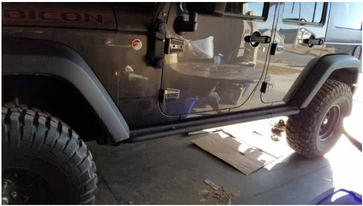
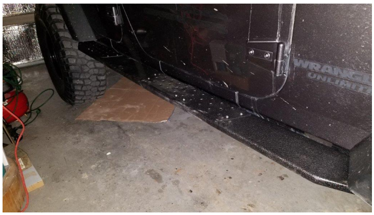
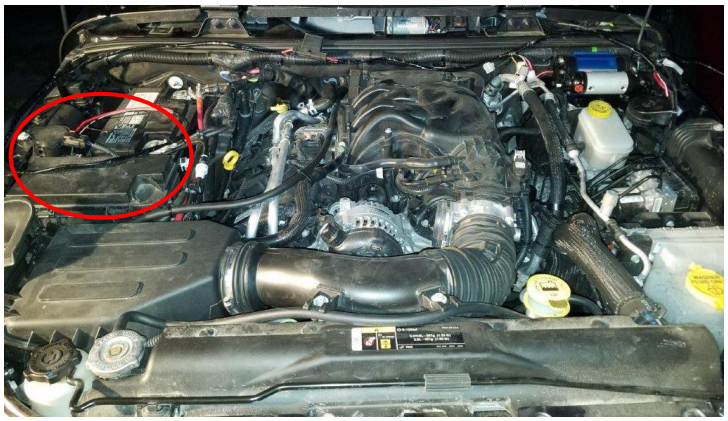
Before Picture
Wiring Details
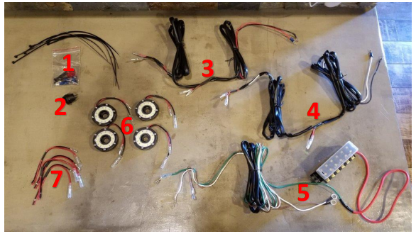
1. Fuses and terminals
2. On/Off switch (Not needed if you have a switch pod)
3. Short side light wiring
4. Long side light wiring
5. Fuse block and switch wires (Not needed if you have a switch pod)
6. Rock lights
7. Spare rock light terminals (Not needed unless you aren’t using wires #3 and #4)
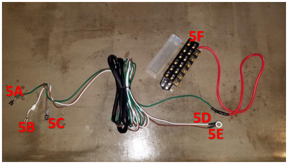
5A: Connects to switch middle terminal
5B: Connects to switch bottom terminal
5C: Connects to switch top terminal
5D: White wire: Connects to battery positive
5E: Brown wire: Connects to battery negative
5F: Fuse block for supplied fuses
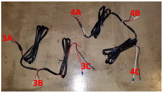
3A: Connects to the driver rear rock light (red to red, black to black)
3B: Connects to the driver forward rock light (red to red, black to black)
3C: Connects to power (black to battery negative, red to the provided fuse block) (If you have your own switch pod, connect these to your switch pod, black to negative, red to positive)
4A: Connects to the passenger rear rock light (red to red, black to black)
4B: Connects to the passenger forward rock light (red to red, black to black)
4C: Connects to power (black to battery negative, white to the provided fuse block) (If you have your own switch pod, connect these to your switch pod, black to negative, white to positive)
Installation Instructions
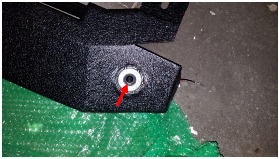
1. Using a 5mm hex wrench attach all 4 rock lights using the supplied hardware as shown.
2. Start on the driver side. Using a 13mm socket remove the 3 bolts holding the stock rubi-rails to the frame. Using a 10mm socket remove the 6 nuts holding the rubi-rails to the pinch weld. Then you remove your stock rubi-rails.
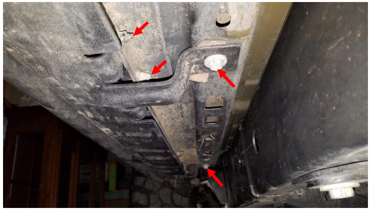
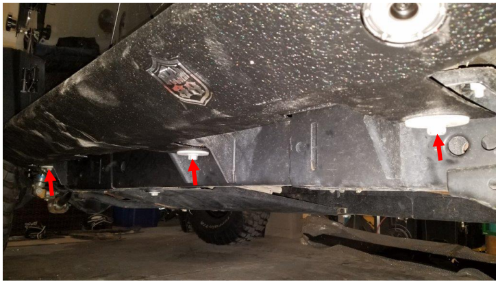
3. Using an 18mm socket remove the 3 body mount bolts shown below.
4. Next, have a friend hold the new rock slider in place and hand tighten all 3 body mount bolts.
Note: The rock sliders are diver/passenger side specific, so choose the one that matches your body mount bolts holes.
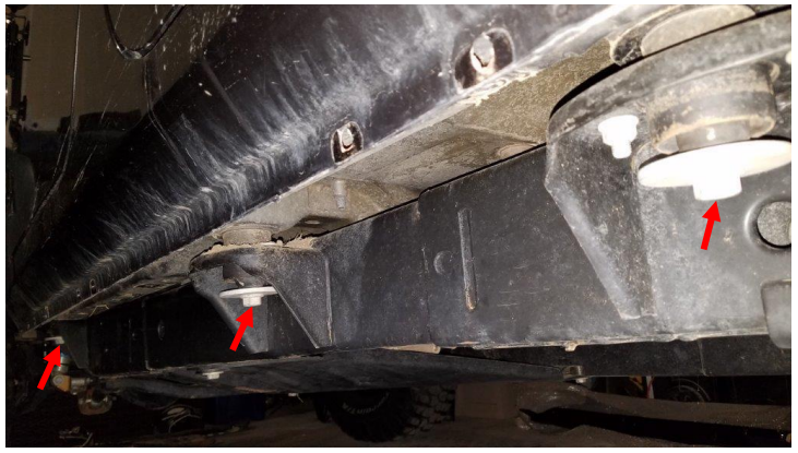
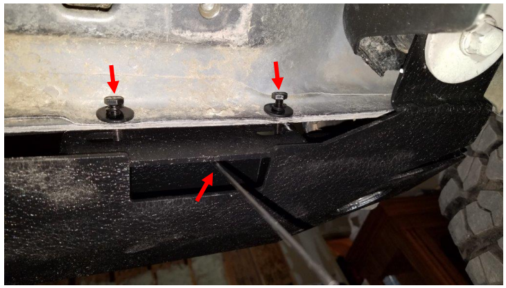
5. Now use the supplied nut plates on sticks and supplied hardware. Insert the nut plate though the slot using the stick to align the bolt holes. Then hand tighten the supplied bolts as shown. Repeat this for all 3 nut plates
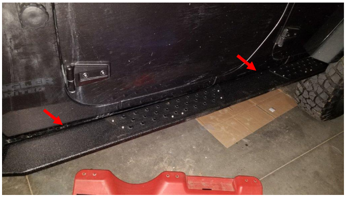
6. Now check how the top of the step fits against the Jeep body. The step should not touch the body as it will rub through the paint. If it touches the body or doesn’t fit strait you may need to add some of the supplied spacers.
Note: In this step and the next step you will need to tighten the pinch seam bolts to see where the steps end up, then you will need to loosen them if you need a spacer.
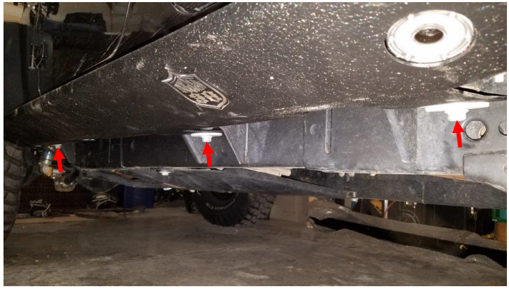
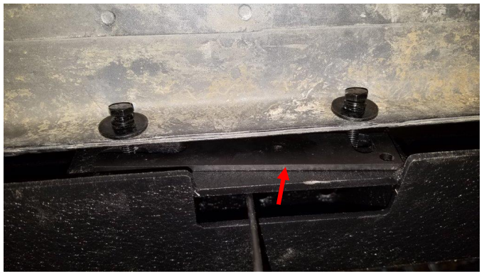
7. If you need spacers, loosen the pinch seam bolts and insert the spacers as shown. The spacers have 2 slots so you do not have to completely remove the bolts to insert the spacers.
Note: You may need different spacers for each joint on the same step. For example, mine needed a small spacer in the rear and middle, and no spacer up front.
8. Once you have determined what spacers you need, use a 10mm socket to tighten all 6 pinch seam bolts. Then break off all 3 nut plate sticks.
9. Next using an 18mm socket and torque wrench, tighten all 3 body mount bolts to 80ft/lbs.
10. Repeat steps 2-9 on the passenger side.
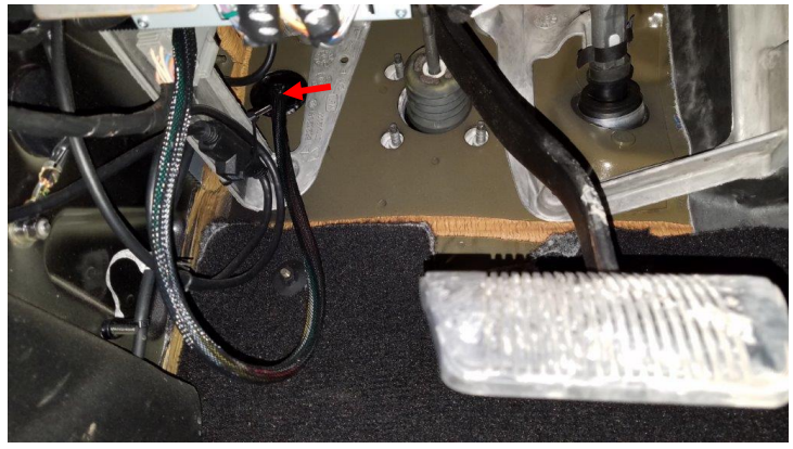
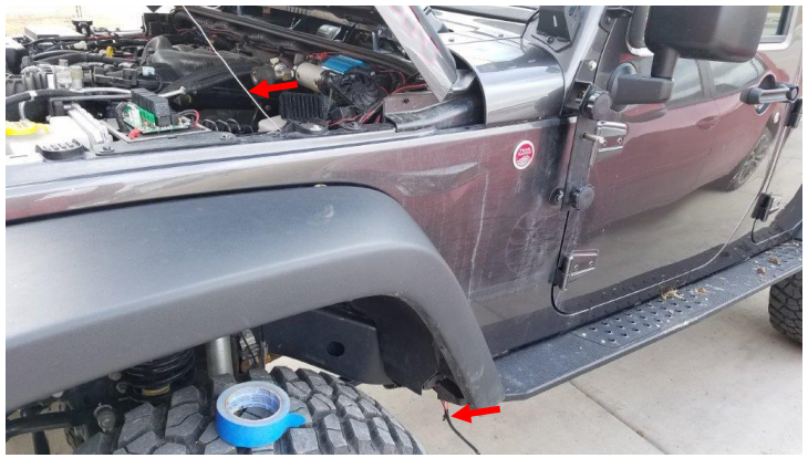
11. If you are using your own switch pod, skip to step 14. If you are using the supplied fuse block and switch continue with this step. Behind the brake pedal find the black gasket shown below. Poke a small hole through it. Then use a straightened wire hanger. Push it through to the engine bay. From the engine bay, tape wires 5A, 5B, and 5C to the hanger, then pull them through to the cab.
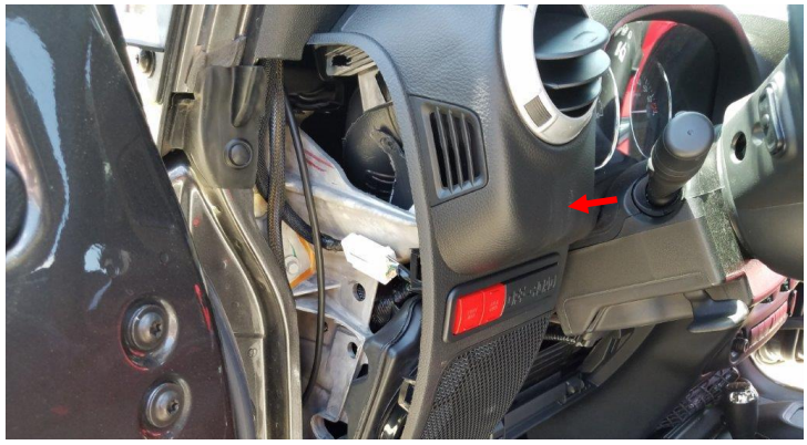
12. Find a spot to mount your switch. Then drill a ¾” hole. Route the wires to your switch hole. Connect the wires as described at the beginning of this guide. Then push your switch into place in the new hole you drilled.
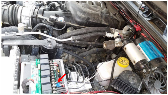
13. Mount the supplied fuse block wherever you like. I recommend using an existing bolt somewhere on the passenger side of the engine bay. Then route the wires up out of the way, and connect them to the battery, 5D to positive, 5E to negative. Use the supplied zip ties to hold the wires in a safe place.
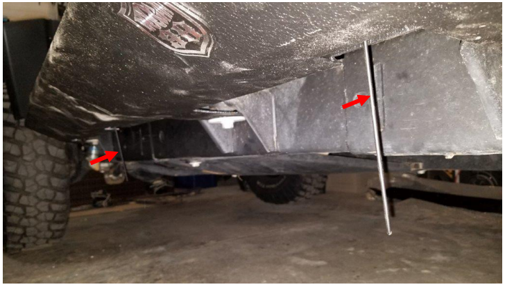
14. Next use a wire hanger to pull wire 3C or 4C up though the wheel well as shown. It helps if you tape the wire to the hanger.
Note: If your switch pod is on the driver side use wire 3C. If you used the supplied fuse block or your switch pod is on the passenger side, use wire 4C.
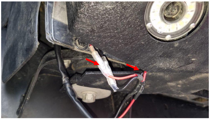
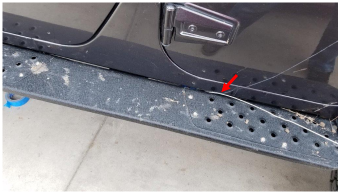
15. Connect wires 3B or 4B to the driver front rock light as shown. Then route the rest of the wire up into the rock slider as shown.
16. Next, use the wire hanger to pull wire 3A or 4A through to the rear driver rock light. Then connect them to the rock light.
17. Repeat steps 14-16 on the passenger side.
18. Then connect 3C and 4C to power. If you are using your own switch pod, connect them to the desired terminals as shown below. If you are using the supplied fuse block, connect the black wires to the battery negative, and the red/white wires to the fuse block.
19. Last, turn on your switch and make sure all 4 of them work!
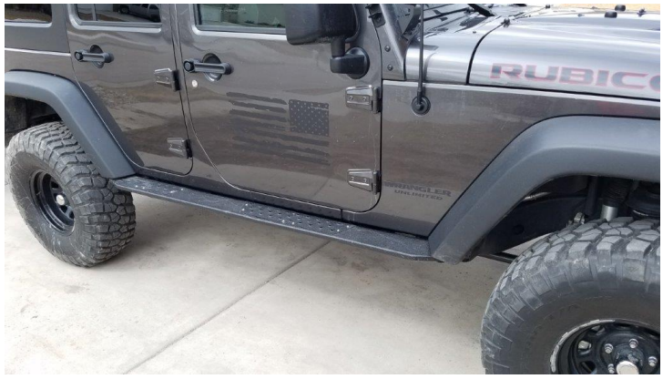
After Picture
Installation Instructions Written by ExtremeTerrain Customer John Parker 03/28/2018

